Thus, each relay
station can only send and receive signals from a limited distance.
The distance that the radio signals can travel is limited because of
horizon problems due to the curvature of the earth;
line of sight problems due to uneven
terrain, trees, and buildings; interference due to other signals or with reflections of the transmitted
signal; and attenuation problems due to unwanted absorption of the transmitted
signal.
Increasing power helps to solve the attenuation problem and the interference with other signals problem; but it does not address the horizion, line-of-
sight, and interference with relected
signal problems.
However, it is not always feasible to place relay stations at optimum locations due to geographic or political factors, or merely because of the inability to obtain permission from a land owner or government.
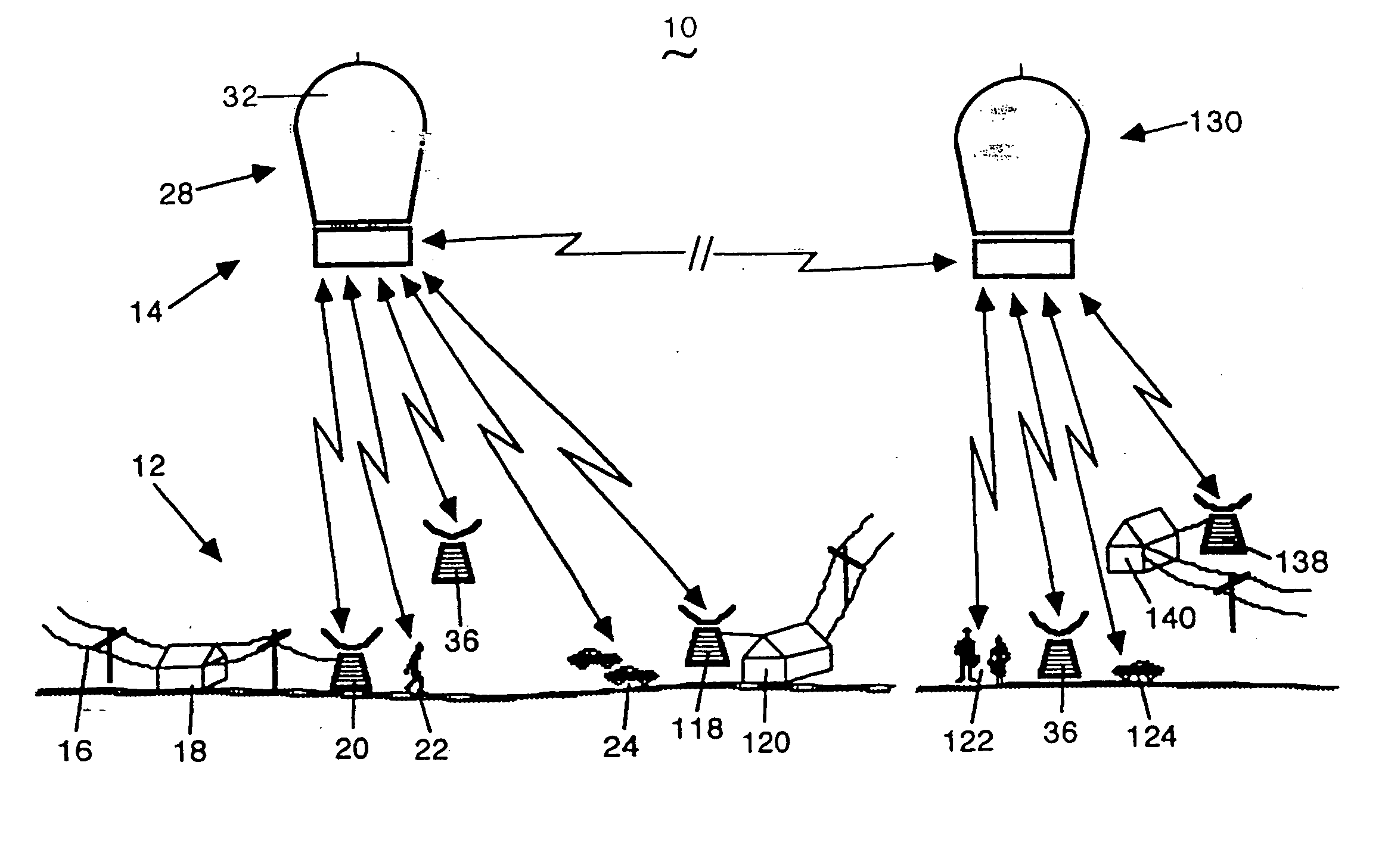
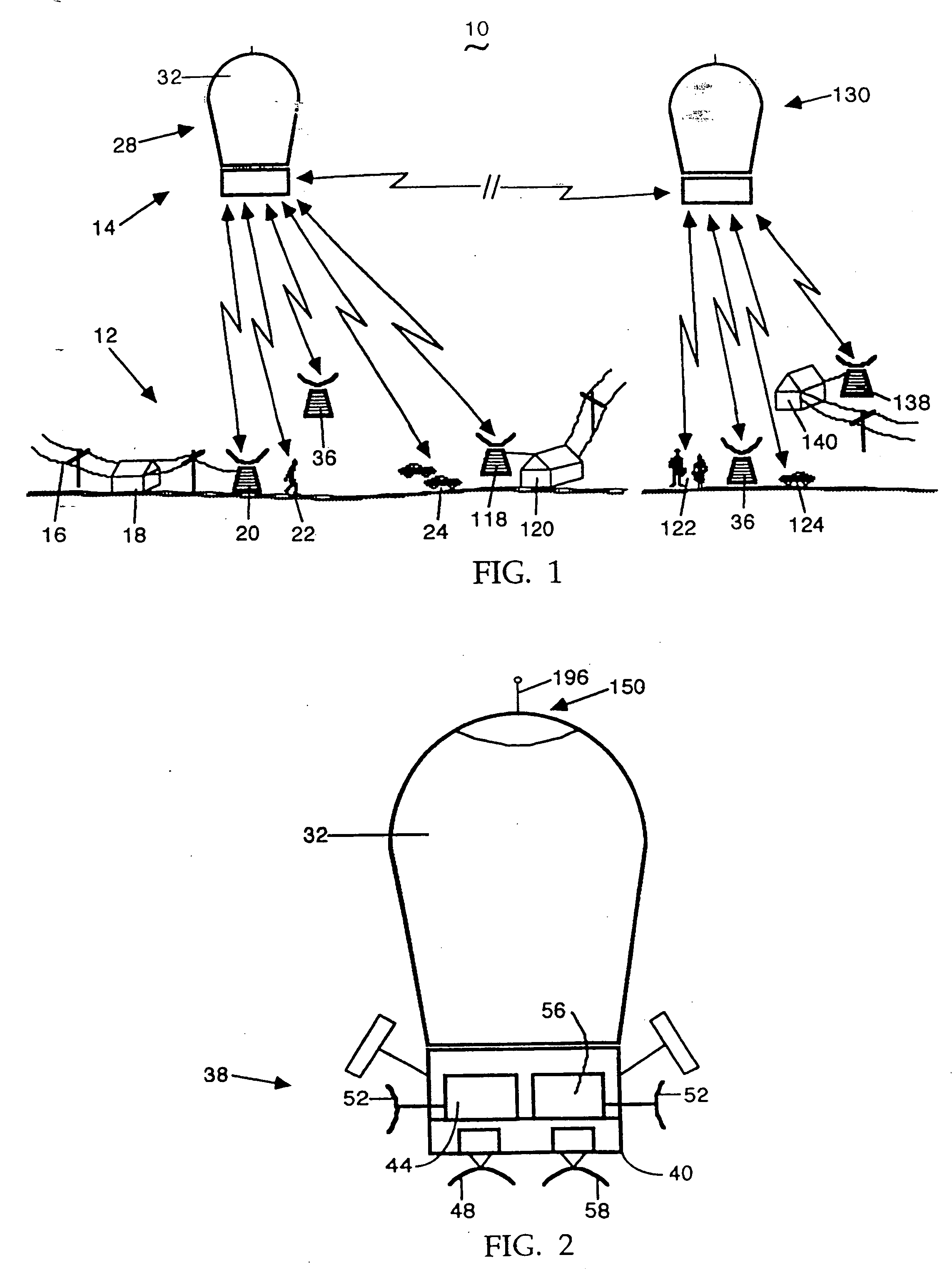
However, tethered balloons have their own problems.
If the balloons are tethered at low altitudes, their area of coverage will not be any larger than that of a relay station on a
tower or tall building making it difficult to justify their cost.
Also, since they will be subject to the weather and wind conditions that exist at these altitudes, they are likely to be easily damaged and require frequent replacement.
On the other hand, if they are tethered at altitudes that enable them to relay telecommunications signals over a large enough area to make them economically feasible and to avoid weather conditions, thereby prolonging their life, both the balloons and tethers become hazardous to aircraft and the tethers remain subject to the stress of weather conditions.
Further, it is likely that the tether of a failed
balloon will be strewn along hundreds if not thousands or tens of thousands of feet causing damage and risk of injury to property and persons.
Additionally, if the tether falls across electric lines there is a risk of fire and power outages.
Accordingly, these disadvantages make tethered ballons unsuitable for use as part of a telecommunications
system whose components are to operate for long periods.
However, satellites are expensive to manufacture, launch and position, either initially or as replacements.
Further, because of the cost associated with their manufacture and launch, and the great difficulty in servicing them, extraordinary care must be taken to assure their reliability.
This significantly limits the
satellite's ability to carry and conduct familiar two way (duplex) voice communications.
Also, due to its high altitude, its
radio transmission equipment requires more power than required by comparable terrestrial systems.
This raises costs and affects the size and weight of equipment both on the satellite and on the ground.
When a satellite fails, as assuredly they all must do, either electronically, or by decay of
orbit, attempts to recover or repair them are extremely expensive.
Further, the attempts, whether or not successful, subject personnel and equipment to the risk of injury or loss.
On the other hand, a failed satellite may be left in
orbit.
If it is not fully consumed during the plunge, it may cause damage to persons or property when it strikes the earth.
While this will reduce power requirements and
transmission delay times, it creates other problems.
Therefore, a particular satellite that is over a
ground station at the beginning of a communication may
orbit to such an extent during the communication that it loses the signal from the ground.
Thus, very complex routing features will need to be implemented.
In addition, members of the industry disagree amongst themselves over optimum altitudes, angles of signal propagation, and how to deal with the doppler shifts.
Furthermore, because of their lower altitude, the satellites' orbits will decay at faster rates than the higher altitude satellites so that they and the equipment they carry will need to be replaced more often, again incurring substantial expense.

