Fuel injection system for internal combustion engine

a fuel injection system and internal combustion engine technology, applied in the direction of liquid fuel feeders, machines/engines, mechanical equipment, etc., to achieve the effect of preventing energy loss and reducing the fuel consumption of internal combustion engines

Inactive Publication Date: 2006-03-30
DENSO CORP
View PDF5 Cites 13 Cited by
  • Summary
  • Abstract
  • Description
  • Claims
  • Application Information

AI Technical Summary

Benefits of technology

[0021] Moreover, since the hydraulic pressure supply passage and the hydraulic pressure release passage are selectively opened and closed by the control valve, the accumulator and the control chamber of the pressure intensifier are not always connected to each other through the hydraulic pressure supply passage. In other words, when the control valve opens the hydraulic pressure release passage, the fuel pressure in the control chamber is released to the low pressure side through the hydraulic pressure supply

Problems solved by technology

Moreover, since the hydraulic pressure supply passage and the hydraulic pressure release passage are selectively opened and closed by the control valve, the accumulator and the control chamber of the pressure intensifier are not always connected to eac

Method used


Image

  • Fuel injection system for internal combustion engine
  • Fuel injection system for internal combustion engine
  • Fuel injection system for internal combustion engine

Examples


first embodiment

Effect of First Embodiment

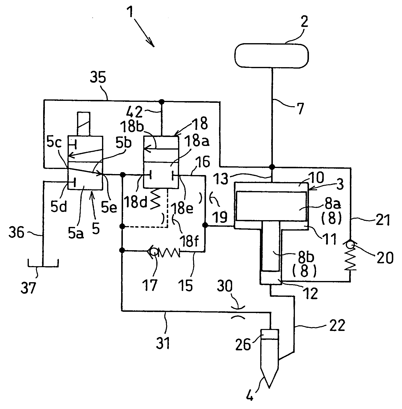
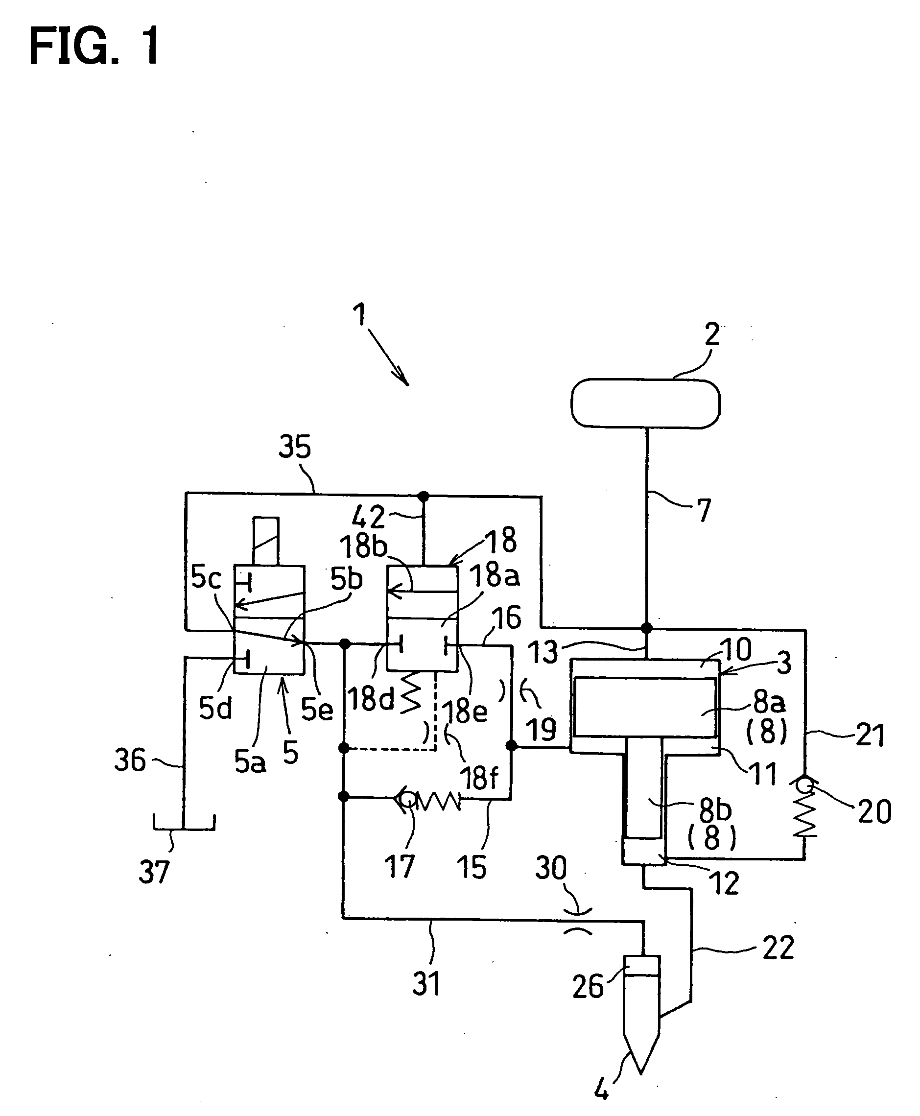
[0065] In the fuel injection system 1 shown in the first embodiment, the control valve 5 is constructed as the two-position three-way valve. Hence, a hydraulic pressure supply passage for supplying the fuel pressure in the accumulator 2 to the control chamber 11 of the pressure intensifier 3 and the backpressure chamber 26 of the injection nozzle 4 and a hydraulic pressure supply passage for releasing the fuel pressure in the control chamber 11 and the backpressure chamber 26 to the low pressure side can be selectively opened or closed by one control valve 5. Moreover, the switching port 5e of the control valve 5 is connected in parallel with the control chamber 11 of the pressure intensifier 3 by two fuel passages 15, 16 and one fuel passage 15 is provided with the check valve 17 to allow the fuel to flow from the control valve 5 to the control chamber 11, whereas the other fuel passage 16 is provided with the hydraulic valve 18 to allow the fuel to flow f...

second embodiment

[0071]FIG. 8 is the hydraulic circuit diagram of the fuel injection system 1 in accordance with the second embodiment.

[0072] The configuration of the fuel injection system 1 shown in this second embodiment is different from the configuration of the first embodiment in that the other fuel passage 16 for connecting the switching port 5e of the control valve 5 with the control chamber 11 of the pressure intensifier 3 is provided with a check valve 43. In other words, in the first embodiment, the other fuel passage 16 is provided with the hydraulic valve 18, but in this second embodiment, the check valve 43 is provided in place of the hydraulic valve 18. Moreover, while the one fuel passage 15 is provided with the restrictor 19 in FIG. 8, as is the case with the first embodiment, the other fuel passage 16 may be provided with the restrictor 19 or both of the fuel passages 15, 16 may be provided with the restrictors 19, respectively.

[0073] Also in this second embodiment, a passage (one...

third embodiment

[0075]FIG. 9 is the hydraulic circuit diagram of the fuel injection system 1 in accordance with the third embodiment.

[0076] The fuel injection system 1 shown in this third embodiment is an example in which the action of the pressure intensifier 3 and the action of the injection nozzle 4 are controlled by two control valves (the first control valve 4 and the second control valve 45).

[0077] The two control valves are the first control valve 44 provided in a hydraulic pressure supply passage 46 for supplying the fuel pressure in the accumulator 2 to the control chamber 11 of the pressure intensifier 3 and the backpressure chamber 26 of the injection nozzle 4 and the second control valve 45 provided in a hydraulic pressure release passage 47 for releasing the fuel pressure in the control chamber 11 and the backpressure chamber 26 to the low pressure side.

[0078] The first control valve 44 has a valve body 44a driven by a two-position actuator and this valve body 44a is a two-position ...


PUM


Abstract

A control valve is constructed as a two-position three-way valve. A switching port of the control valve and a control chamber of a pressure intensifier are connected to the control valve through a reciprocation passage. Fuel pressure in the control chamber is controlled by the control valve. The reciprocation passage is formed of two fuel passages for connecting the switching port of the control valve with the control chamber in parallel. One fuel passage is provided with a check valve for preventing fuel from flowing from the control chamber to the control valve and the other fuel passage is provided with a hydraulic valve for preventing the fuel from flowing from the control valve to the control chamber and a restrictor.

Description

CROSS-REFERENCE TO RELATED APPLICATION [0001] This application is based on Japanese Patent Application No. 2004-279494 filed on Sep. 27, 2004, the disclosure of which is incorporated herein by reference. BACKGROUND OF THE INVENTION [0002] 1. Field of the Invention [0003] The present invention relates to a fuel injection system for an internal combustion engine, in particular, for a diesel engine. [0004] 2. Description of the Related Art [0005] A common rail system is known as a fuel injection system for an internal combustion engine. This common rail system is a system that includes an accumulator (common rail) for accumulating fuel in the state of a specified pressure and injects high-pressure fuel supplied by the accumulator into the cylinder of the internal combustion engine by an injector and has excellent performance of controlling an injection pressure and an injection quantity independently. In recent years, from the viewpoint of cleaning exhaust gas and decreasing fuel consu...

Claims


Application Information

Patent Timeline
IPC IPC(8): F02M57/02
CPCF02M47/027F02M61/205F02M57/025
Inventor YAMAMOTO, YOSHIHISA
Owner DENSO CORP
Why Eureka
Try Eureka