Monitoring light beam position in electro-optical readers and image projectors

a technology of image projectors and light beams, which is applied in the direction of mirrors, instruments, sensing record carriers, etc., can solve the problems of extra hardware, phase delay and annoying sounds, unsatisfactory magnetic coupling between drive and feedback coils, etc., and achieve the effect of eliminating electromagnetic feedback

Active Publication Date: 2006-03-30
MICROVISION
View PDF5 Cites 17 Cited by
  • Summary
  • Abstract
  • Description
  • Claims
  • Application Information

AI Technical Summary

Benefits of technology

[0009] Accordingly, it is a general object of this invention to eliminate electromagnetic feedback in light scanning arrangements, such as electro-optical readers and image projectors.

Problems solved by technology

Although generally satisfactory for its intended purpose, the use of the feedback coil for monitoring for drive failure, for driving the drive, and for generating the SOS signal causes problems.
There is undesirable magnetic coupling between the drive and feedback coils.
As in the case of readers, the drive includes a motor having feedback and drive coils, as described above, with their attendant problems of cross-coupled signals, extra hardware, phase delays and annoying sounds.

Method used


Image

  • Monitoring light beam position in electro-optical readers and image projectors
  • Monitoring light beam position in electro-optical readers and image projectors
  • Monitoring light beam position in electro-optical readers and image projectors

Examples


Embodiment Construction

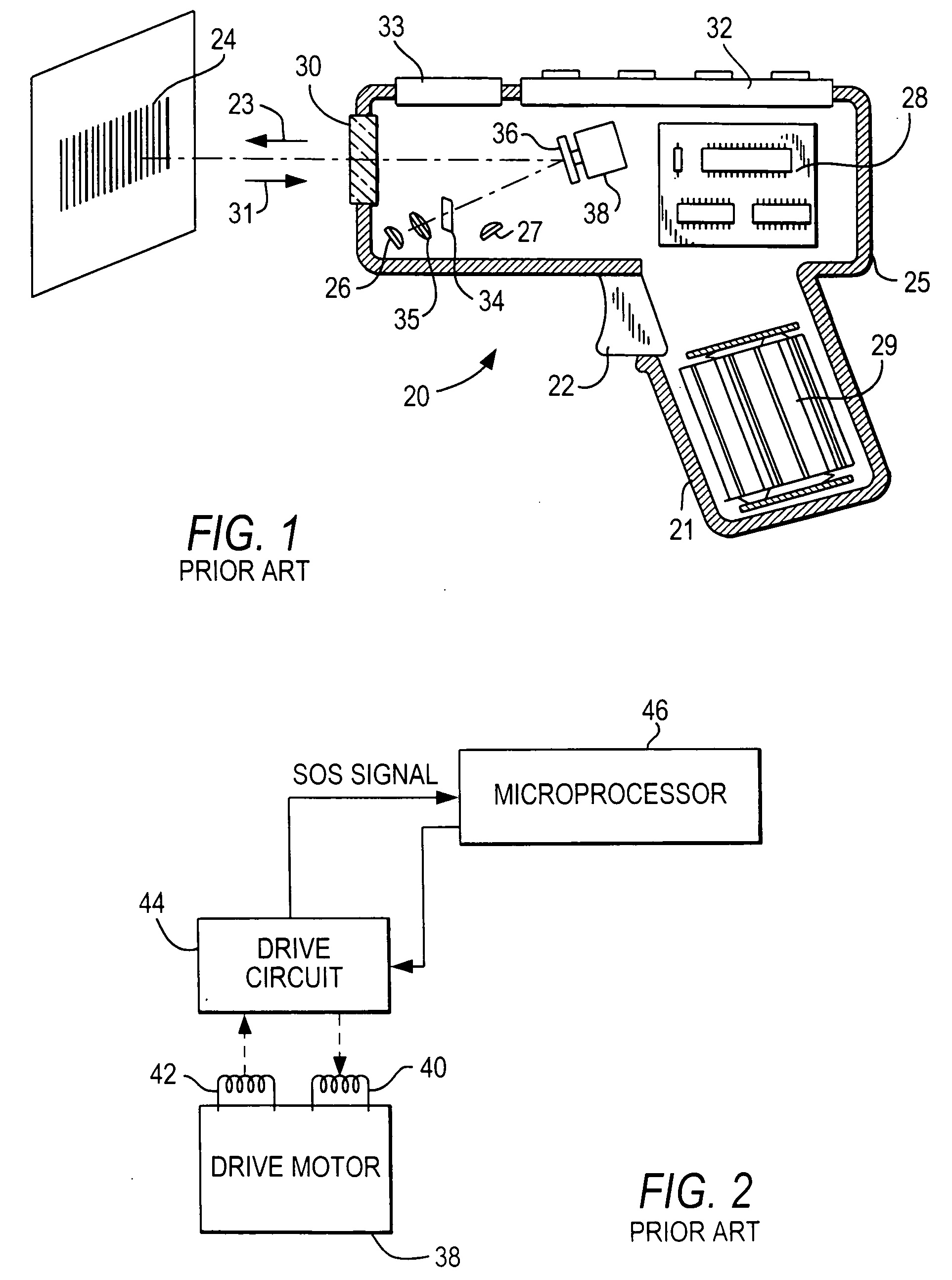
[0036] Reference numeral 20 in FIG. 1 generally identifies a prior art hand-held reader for electro-optically reading indicia, such as bar code symbol 24, located in a range of working distances therefrom. The reader 20 has a pistol grip handle 21 and a manually actuatable trigger 22 which, when depressed, enables a light beam 23 to be directed at the symbol 24. The reader 20 includes a housing 25 in which a light source 26, a light detector 27, signal processing circuitry 28, and a battery pack 29 are accommodated. A light-transmissive window 30 at a front of the housing enables the light beam 23 to exit the housing, and allows light 31 scattered off the symbol to enter the housing. A keyboard 32 and a display 33 may advantageously be provided on a top wall of the housing for ready access thereto.

[0037] In use, an operator holding the handle 21 aims the housing at the symbol and depresses the trigger. The light source 26 emits a light beam which is optically modified and focused b...


PUM


Abstract

An arrangement for determining light beam position in an electro-optical reader, image projector and like devices includes a drive for moving a scanning light beam at a scan frequency across a target as a scan line, and an electro-optical feedback assembly operatively connected to the drive, for optically detecting scan line position during beam movement, and for generating a feedback signal at the scan frequency, the feedback signal being indicative of the scan line position. A feedback coil in the drive is eliminated to avoid electromagnetic coupling between multiple coils in the drive.

Description

BACKGROUND OF THE INVENTION [0001] 1. Field of the Invention [0002] The present invention generally relates to monitoring light beam position of scanning light beams employed in electro-optical readers for reading indicia such as bar code symbols, or in image projectors for displaying images and, more particularly, to employing optical feedback to determine beam position. [0003] 2. Description of the Related Art [0004] Electro-optical readers are well known in the art for electro-optically transforming a spatial pattern of graphic indicia, known as a symbol, into a time-varying electrical signal which is then decoded into data. Typically, a light beam generated from a light source is focused by a lens along an optical path toward a target that includes the symbol. The light beam is repetitively swept along a scan line or a series of scan lines arranged in a raster pattern over the symbol by moving a scan mirror or some other optical component located in the optical path, or by movin...

Claims


Application Information

Patent Timeline
Patent Type & Authority Applications(United States)
IPC IPC(8): G06K7/10
CPCG06K7/10702G06K7/10683
Inventor LI, YAJUNDVORKIS, PAULYAVID, DMITRIYWOOD, FREDERICK F.STERN, MIKLOSBARKAN, EDWARDNAMBUDRI, NARAYAN
Owner MICROVISION
Why Eureka
Try Eureka