Two-stage injector-mixer

a two-stage, injector technology, applied in the direction of dispersed particle separation, separation process, transportation and packaging, etc., can solve the problems of not producing as many bubbles, clogging of art devices with pollutants, and not being practical in the home environment. , to achieve the effect of easy formation, easy production and increased exposure of pollutants

Inactive Publication Date: 2006-03-30
ARROYO MARIBEL
View PDF10 Cites 15 Cited by
  • Summary
  • Abstract
  • Description
  • Claims
  • Application Information

AI Technical Summary

Benefits of technology

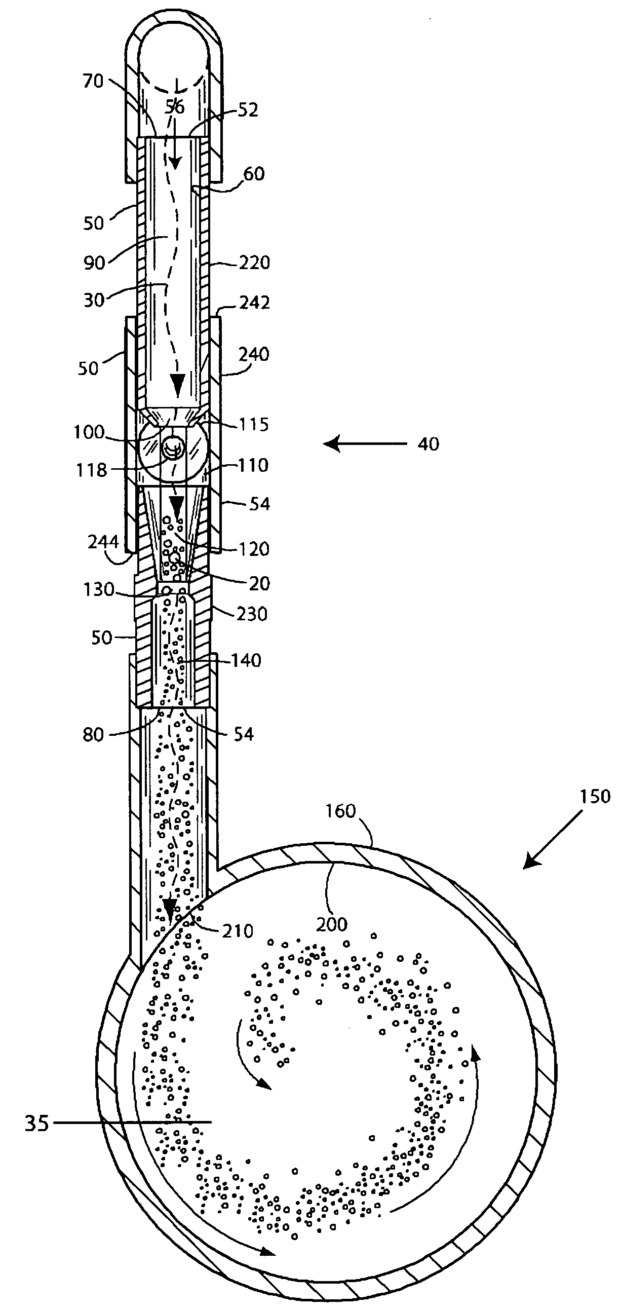
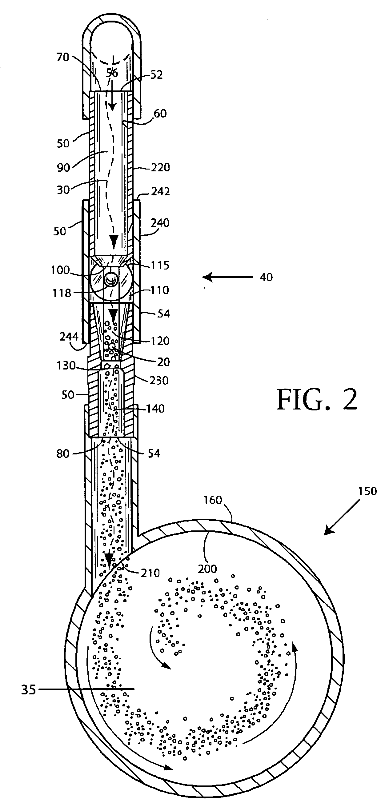
[0012] The mixing section comprises a generally cylindrical vortex chamber with an open end and a closed end. A mixing chamber extends through the cylindrical vortex chamber from the open end and terminates at the closed end. The mixing chamber is defined by a circularly section wall extending along a central axis of the cylindrical vortex chamber from the open end to the closed end. The mixture inlet port enters the mixing chamber through the wall immediately adjacent to the closed end and tangentially to the wall. As such the mixture swirls around the mixing chamber to promote greater exposure of the pollutants in the water with the air, before the mixture exits the mixing section at the open end and enters the protein skimmer column.
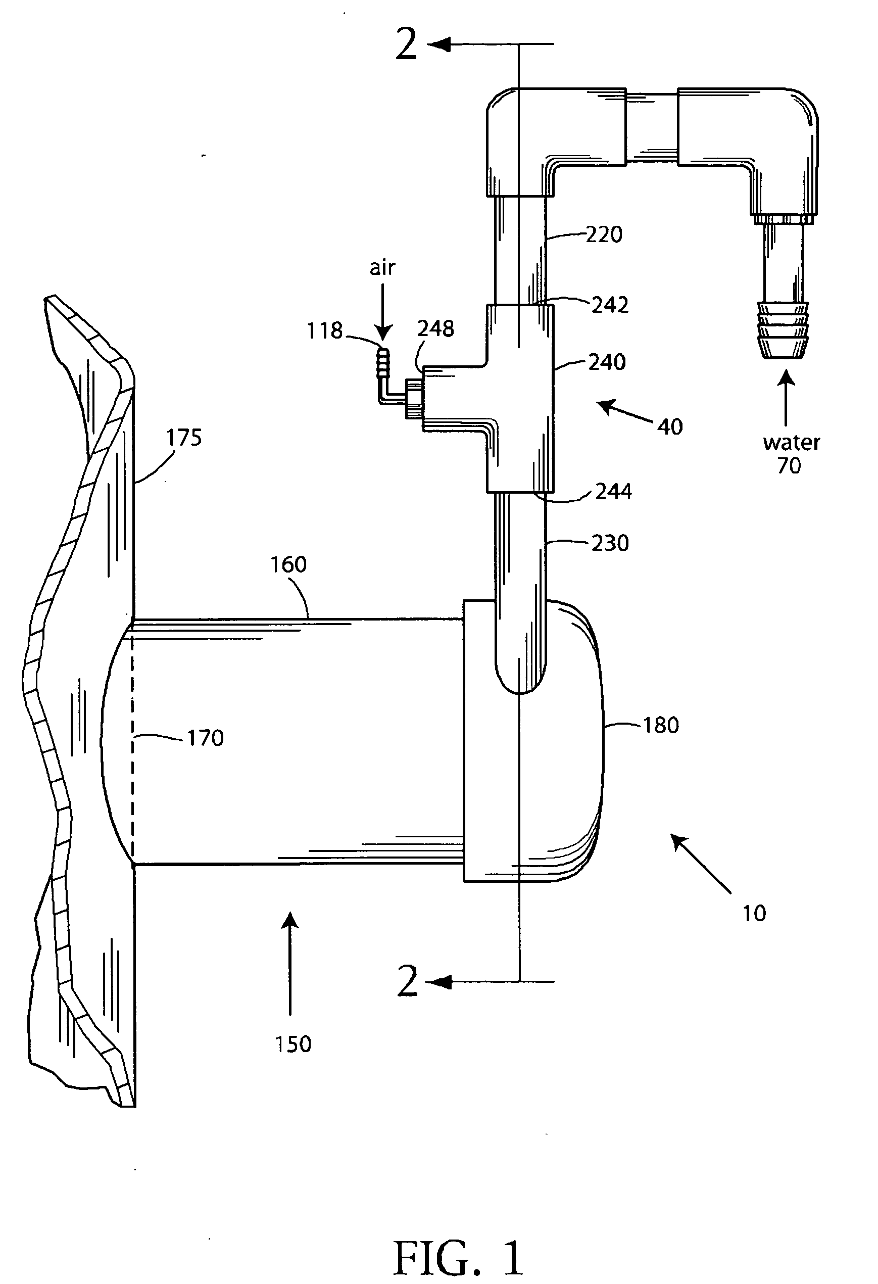
[0013] The entry portion and nozzle portion of the injection section may be readily formed by turning a thick-walled PVC pipe, or the like, on a lathe. In larger quantities, such an inlet pipe is easy to produce with injection molding. Further, and in a similar manner, an exit pipe may be formed that includes the funnel portion, the expanding portion, and the exit portion. Both such inlet and exit pipes may be joined with a standard T-shaped connector that holds the inlet and exit pipe in coaxial alignment, the injection portion being formed naturally by the gap between the inlet and exit pipes when so joined. The third opening of the T-shaped connector is then fitted with a gas inlet port to complete the injection assembly. As such, the injection assembly may be manufactured very inexpensively. Such an injection assembly does not suffer from contaminants plugging the air inlet port due to the size of the inlet port. Yet, at the same time, the mixture of water and air does not back-up into the air inlet port due to the shape of the funnel portion and the subsequent expanding portion. Mounting the injection section vertically with the flow of water downward further prevents water from backing-up into the air inlet port, as gravity further compels the water and air mixture down into the mixing section.

Problems solved by technology

Moreover, such prior art devices require a tall “downdraft” tube that is not often practical in a home environment.
However, such prior art devices tend to clog with pollutants at the air injection point into the water stream, and do not produce as many bubbles as the downdraft type protein skimmers.
However, such a device requires an auxiliary tank and takes up considerable space.

Method used


Image

  • Two-stage injector-mixer
  • Two-stage injector-mixer
  • Two-stage injector-mixer

Examples


Embodiment Construction

[0017] The present invention is an injector and mixer device for injecting a gas 20 into a liquid stream 30, and then thoroughly mixing the gas 20 and the liquid 30 before introducing the mixture thereof into a protein skimmer column 175. FIG. 1 illustrates the device, which comprises an injection section 40 and a mixing section 150, and shows a partial protein skimmer column 175 as is common in the fish aquarium filter industry. With the liquid 30 being a mixture of water and pollutants from a fish tank (not shown), and with the gas 20 preferably being ambient air at ambient pressure, stream of liquid 30 flows down through the injector-mixer of the present invention and to be thoroughly mixed with a great multitude of tiny bubbles of gas 20 that serve to bond with the pollutants of the liquid, the pollutants becoming buoyant as a result. Upon introduction of the liquid-air 20, 30 mixture into the protein skimmer column 175, the bubbles of gas 20 and pollutants attached thereto rise...


PUM

PropertyMeasurementUnit
cross-sectional diameteraaaaaaaaaa
sectional diameteraaaaaaaaaa
diameteraaaaaaaaaa

Abstract

An injector-mixer for injecting and thoroughly mixing fine bubbles of air into a contaminated water stream from a fish tank is disclosed. Water is pumped down through an injection section of the present invention where air is injected into the stream by an improved Venturi construction. The mixture then flows into an improved mixing section, where it is thoroughly mixed such that the plethora of small air bubbles have a greater chance to bond with the contaminants of the water, the contaminants becoming buoyant as a result. Upon introduction of the mixture into the protein skimmer column, the bubbles of air and contaminants attached thereto rise to the top of the protein skimmer column to be contained, while the filtered and oxygenated water is returned to the tank.

Description

FIELD OF THE INVENTION [0001] The present invention relates generally to devices for mixing a gas into a fluid stream, and more particularly, to a device adapted to mixing air into an aquarium water line in advance of a protein skimmer. DISCUSSION OF RELATED ART [0002] Protein skimmers for fish aquariums have advanced considerably over the years and are now the favored means of filtering fish tank water. A protein skimmer serves to both introduce very small air bubbles into the aquarium water so as to oxygenate the water for the benefit of the fish, and also to mix air bubbles into the water for the containment of pollutants in the water. Pollutants bond to the air molecules and as a result, become buoyant and are then collected at a top area of the protein skimmer, while the filtered and oxygenated water is returned to the fish tank. [0003] The efficiency of a protein skimmer may be measured by the volume of pollutants filtered from the water in a given period of time, divided by t...

Claims


Application Information

Patent Timeline
Patent Type & Authority Applications(United States)
IPC IPC(8): B01F3/04
CPCA01K63/042B01F3/0446B01F5/0057B01F2003/04879B01F5/106B01F2003/04865B01F5/0413B01F23/232B01F23/23761B01F23/237612B01F25/10B01F25/312B01F25/53B01F23/2326
Inventor SCHLETZ, JUSTIN
Owner ARROYO MARIBEL
Why Eureka
Try Eureka