Plasma display panel and plasma display device

a plasma display and display panel technology, applied in the manufacture of electrode systems, electric discharge tubes/lamps, gas exhaustion means, etc., can solve problems such as noise generation, and achieve the effect of effectively absorbing noise and vibration

Inactive Publication Date: 2006-03-30
SAMSUNG SDI CO LTD
View PDF23 Cites 11 Cited by
  • Summary
  • Abstract
  • Description
  • Claims
  • Application Information

AI Technical Summary

Benefits of technology

[0011] In another embodiment of the invention, a plasma display panel may include a chassis base that is attached to the first plate having the pad by a double-sided tape. In this embodiment, the pad contacts opposing surfaces of the first plate and the chassis base. The pad may contact the outer circumference of the exhaust tube or be interposed between the opposing surfaces of the first plate and t

Problems solved by technology

This resonance results in

Method used


Image

  • Plasma display panel and plasma display device
  • Plasma display panel and plasma display device
  • Plasma display panel and plasma display device

Examples


Embodiment Construction

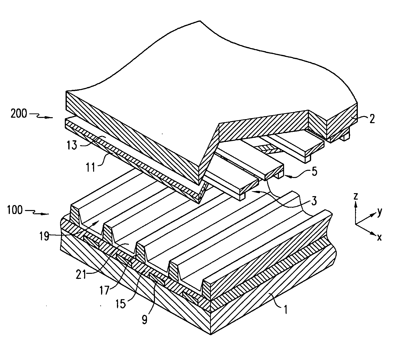
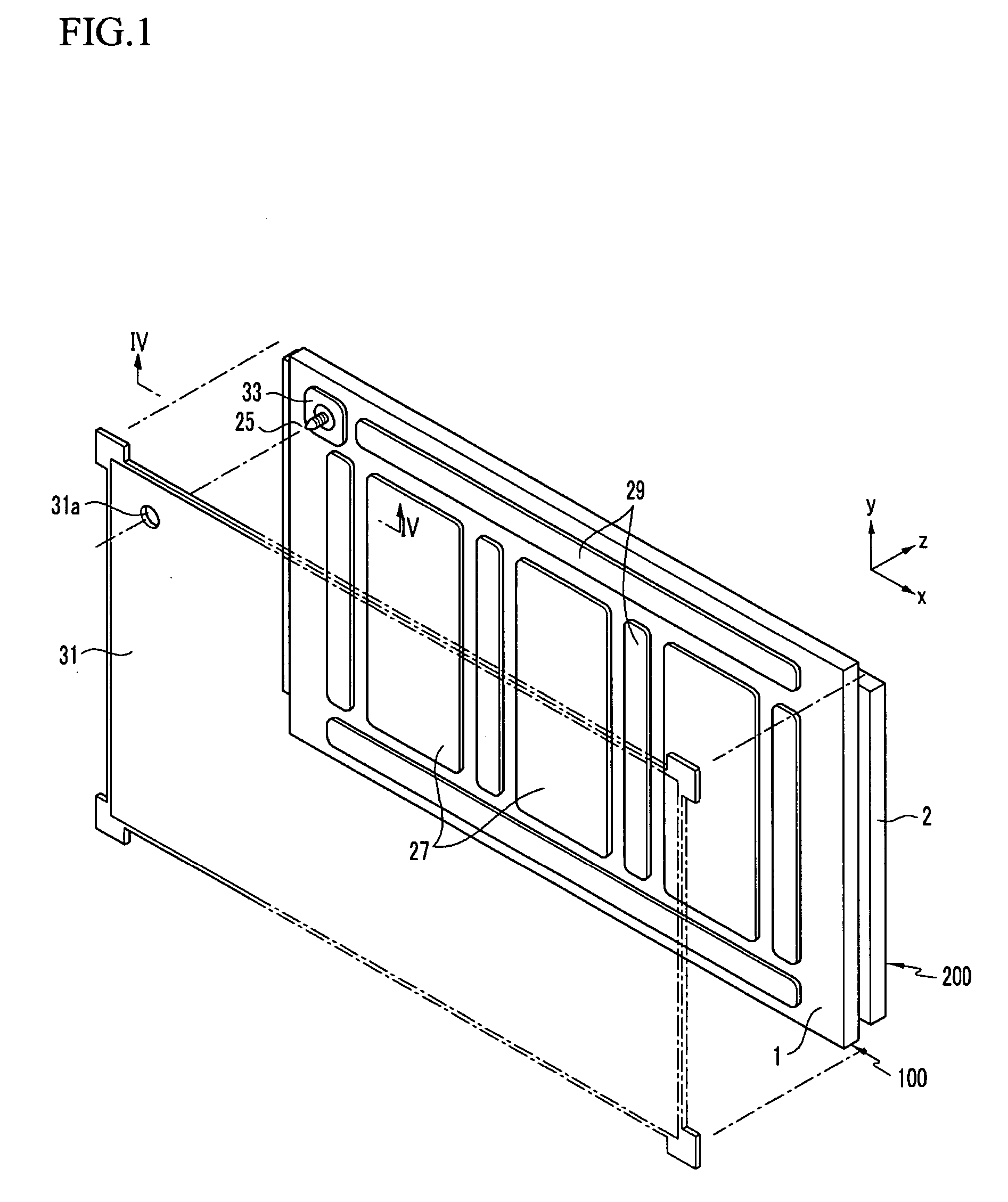
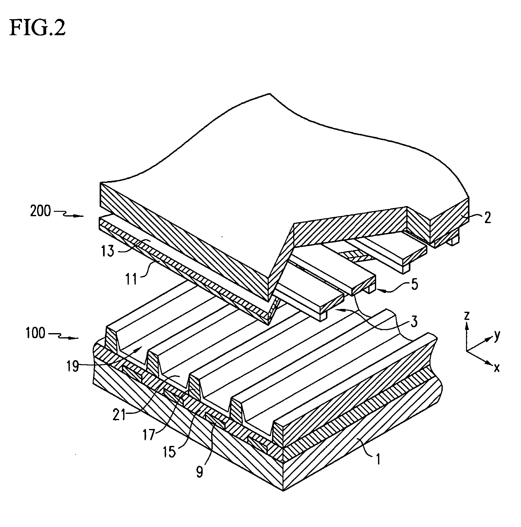
[0017]FIG. 1 is an exploded perspective view of a plasma display device with a plasma display panel and a chassis base according to an embodiment of the present invention, and FIG. 2 is a partially exploded perspective view of the plasma display panel according to the embodiment of the invention.

[0018] Referring to FIGS. 1 and 2, the plasma display panel (“PDP”) according to an embodiment of the invention includes discharge cells 19 that generate images by using gas discharge therein. The discharge cells 19 are formed by sealing a first plate 100 (hereinafter, referred to as a ‘rear plate’) to a second plate 200 (hereinafter, referred to as a ‘front plate’). The height of the discharge cells 19 is considerably smaller than those of the rear plate 100 and the front plate 200. Therefore, in FIG. 1, it appears as though a rear substrate 1 and a front substrate 2 are directly sealed to each other.

[0019] The PDP includes a set of sustain electrodes 3 and scan electrodes 5 that serve as...


PUM


Abstract

A plasma display panel that includes a first plate and a second plate that are sealed to each other to form discharge cells. The discharge cells generate images by gas discharge. The plates include an exhaust port that is formed along an edge of the first plate to define a path to connect to the discharge cells, an exhaust tube on the outside of the first plate that is connected to the discharge cells through the exhaust port, and a pad that is formed around the exhaust port and the exhaust tube of the first plate. This structure effectively blocks a noise path around the exhaust port and the exhaust tube formed in the rear plate.

Description

CROSS-REFERENCE TO RELATED APPLICATION [0001] This application claims priority to and the benefit of Korean Patent Application No. 10-2004-0077063 filed in the Korean Intellectual Property Office on Sep. 24, 2004, the entire content of which is incorporated herein by reference. BACKGROUND OF THE INVENTION [0002] (a) Field of the Invention [0003] The embodiments of the present invention relate to a plasma display panel in a plasma display device, and more particularly, to a plasma display panel in a plasma display device that is capable of effectively blocking a path of noise around an exhaust port and an exhaust tube. [0004] (b) Discussion of the Related Art [0005] Generally, a plasma display panel (PDP) is formed from a front plate and a rear plate that are sealed to one another to hold a discharge gas inside. The front plate includes a front substrate, display electrodes formed on a rear surface of the front substrate, a dielectric layer covering the display electrodes, and a prot...

Claims


Application Information

Patent Timeline
IPC IPC(8): H01J17/49H01J11/12H01J11/24H01J11/26H01J11/36H01J11/38H01J11/40H01J11/42H01J11/46H01J11/48H01J11/50
CPCH01J11/54H01J11/12
Inventor WOO, SEOK-GYUN
Owner SAMSUNG SDI CO LTD
Why Eureka
Try Eureka