
Robust and broadband signal processing using replica generation apparatus

a replica generation and signal processing technology, applied in the direction of speed/acceleration/shock measurement, communication jamming, instruments, etc., can solve the problems of loss of characteristic properties of components in simultaneous signals, difficult fabrication of narrow-band filters in high frequencies, and inability to capture complete information contained in simultaneous signals. , to achieve the effect of limiting teaching, low cost and high precision

Inactive Publication Date: 2006-03-30
LI MING CHIANG
View PDF31 Cites 2 Cited by
  • Summary
  • Abstract
  • Description
  • Claims
  • Application Information

AI Technical Summary

Benefits of technology

[0024] Advantageously, embodiments of the present invention are methods and apparatus that solve the problems listed above in the art and provide low cost, robust, broadband, optimum, high precision methods and apparatus of processing pulsed, transient, non-cooperative, complex, or simultaneous signals. The objective in citing a summary here is for illustration only. It is not intended to be exhaustive or to limit the teaching.

Problems solved by technology

Conventional RF receivers in interferoceivers of prior art cannot capture complete information contained in a simultaneous signal.
It is difficult in fabricating the narrow-band filters in high frequencies.
Although channelized receivers are able to determine frequencies, the characteristic properties of components in simultaneous signals are lost.
This is a problem of the channelized receivers.
Due to the large number of filters and local oscillators, the prior art channelized receivers are expensive to fabricate, bulky in size, and difficult to maintain.
But it is still not able to overcome the problems of the large number of narrow-band filters, and the difficulty in configuring them.
This is another problem for the channelized receivers.
This is not only expensive but also induces the noise and alters the characteristic properties of signal components.
Channelized receivers could not overcome such degradation problems.
This is another further problem for the channelized receivers.
The problems on the channelized receivers still remain the same.
The division between these two types of receivers is due to the problems that channelized receivers are bulky, high cost, and not responsive.
Such a requirement might not be possible.
Furthermore, the operation is time consuming.
Due to the sequential operation, the spectrum analyzer is not effective when signals are pulsed, simultaneous, and non-cooperative.
The problem is that a spectrum analyzer could not function as a channelized receiver.
However, it is not effective when used as a channelized receiver, as the simultaneous signals are non-cooperative and not reproducible.
IF frequency bandwidth is narrow and the local oscillator is not perfectly stable.
Furthermore, down conversion introduces an arbitrary phase into the radar signal and can destroy its coherence.
Hence real radar signals are not simple.
These filters might be able to mimic intended modulations, but they are incapable of mimicking unintended modulations and edge characteristics.
Hence conventional radar receivers cannot lead to most optimum detection of radar signals with the help of matched filters.
The task for detection of non-cooperative or simultaneous signals would be more difficult, as conventional RF receivers do not have a priori knowledge on their intrinsic features.
Hence conventional RF receivers cannot lead to optimum detection of simultaneous signals.
This is a problem of RF digitizers.
The above problem is also the problem for sampling oscilloscopes.
The deficiencies in conventional radar receivers and RF digitizers cause interferoceivers of prior art to be ineffective in most optimum, broadband, robust, and high precision detection of pulsed, transient, non-cooperative, complex, or simultaneous signals.
These deficiencies are problems for interferoceivers of prior art.

Method used


Image

  • Robust and broadband signal processing using replica generation apparatus
  • Robust and broadband signal processing using replica generation apparatus
  • Robust and broadband signal processing using replica generation apparatus

Examples


Embodiment Construction

[0053] The following is a description of an embodiment of the present invention, which provides a broad overview of the present invention.

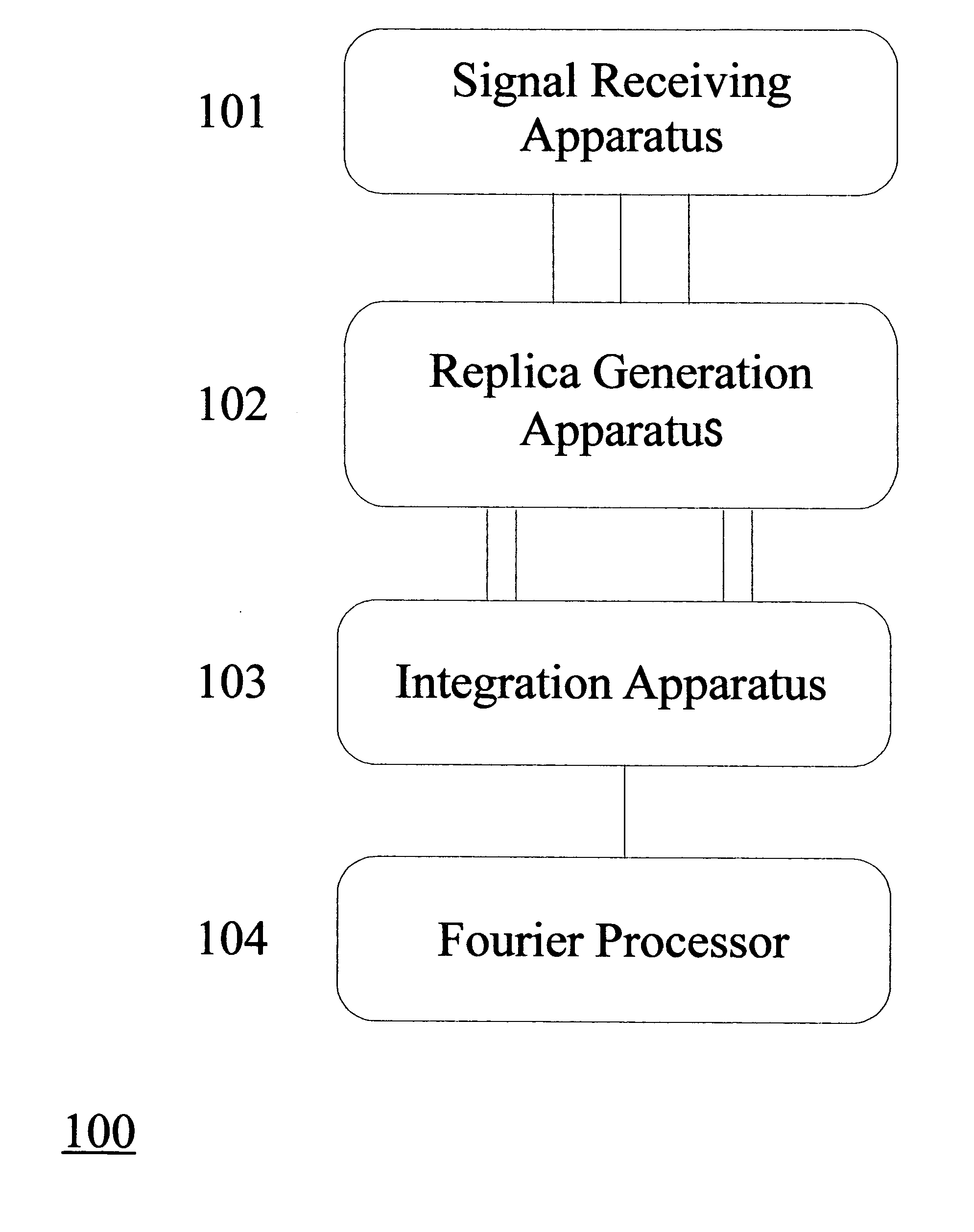
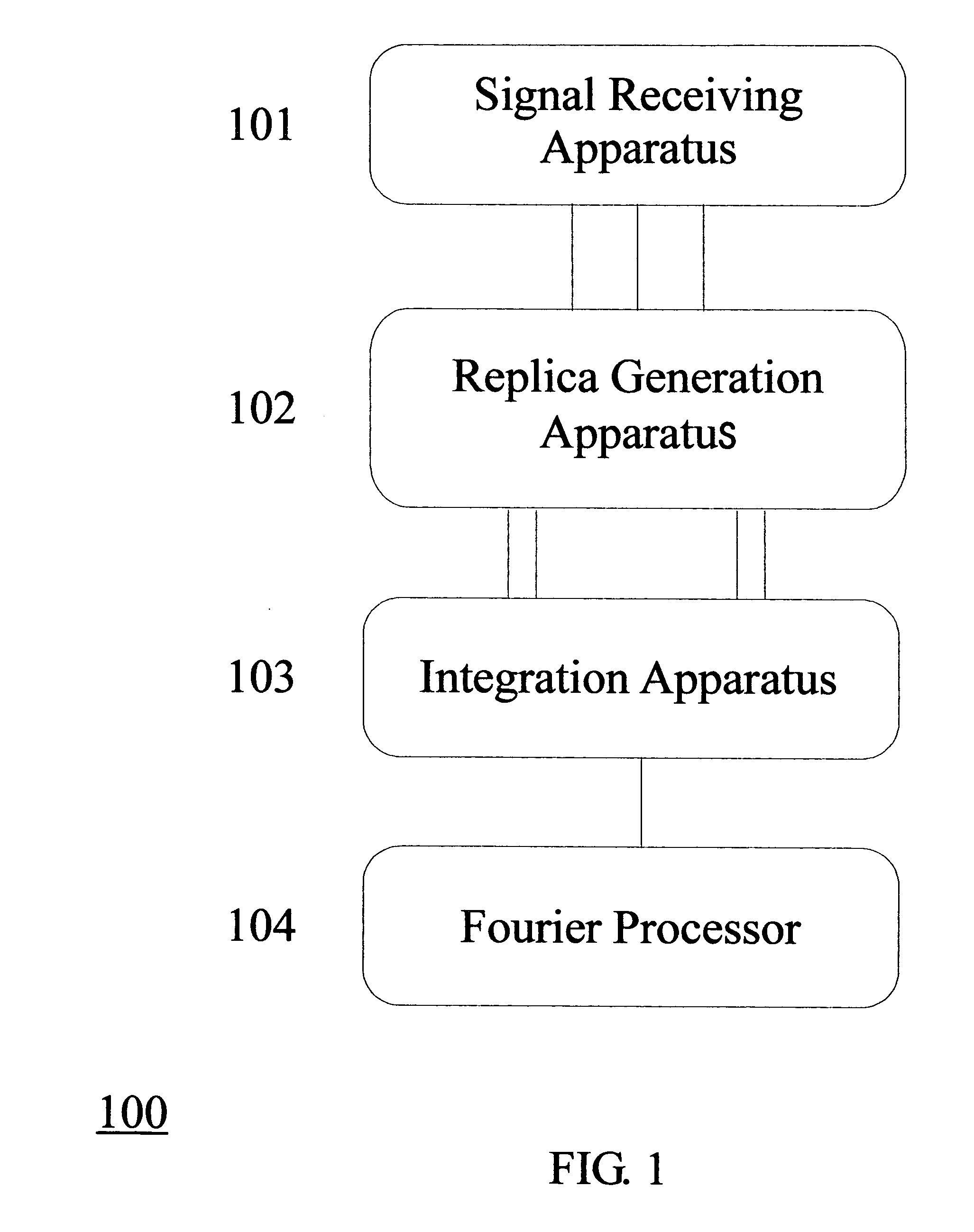
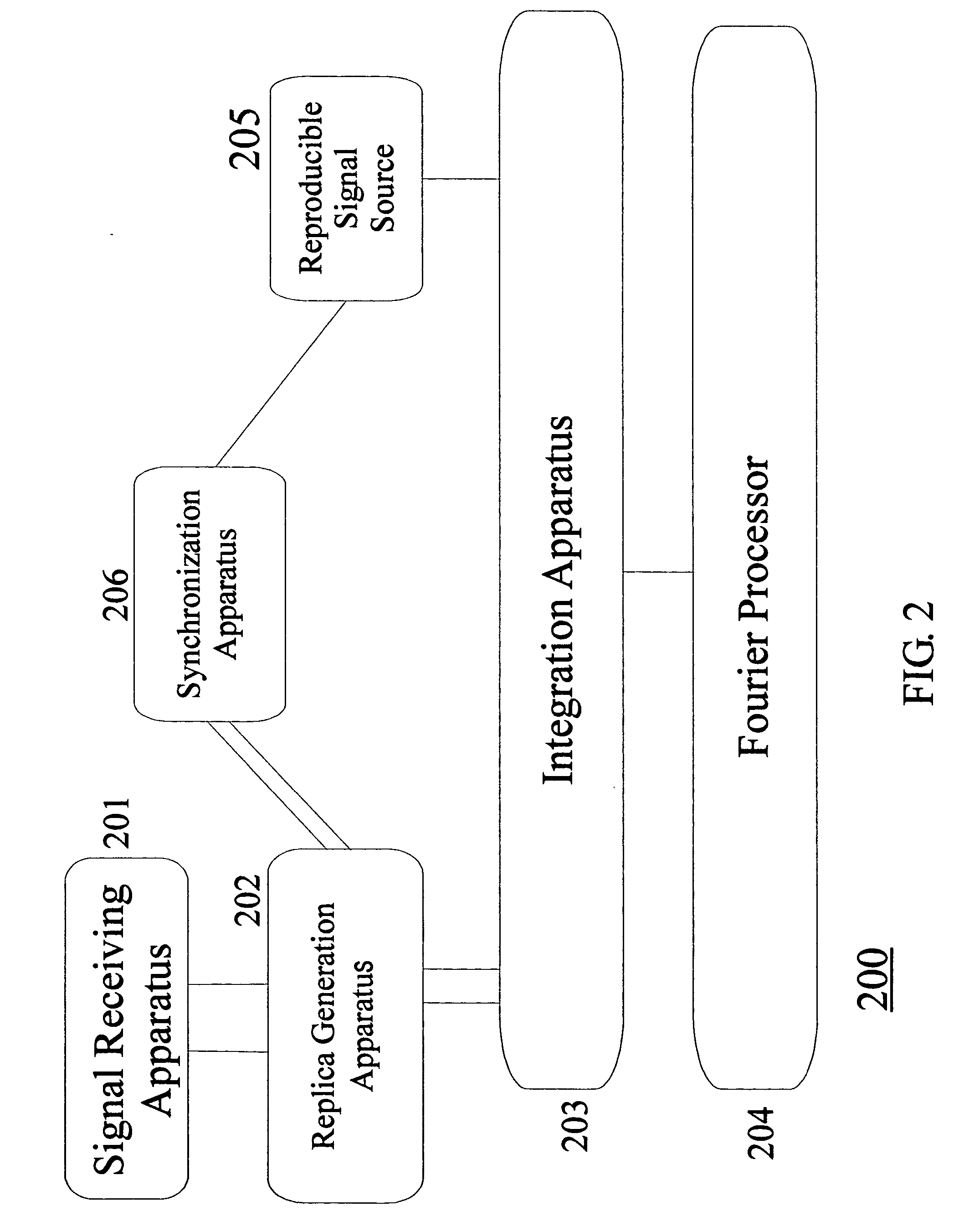
[0054]FIG. 1 shows a block diagram of apparatus 100 for processing pulsed, transient, non-cooperative, non-reproducible, complex, or simultaneous signals in accordance with the present invention. As shown in FIG. 1, apparatus 100 includes the signal receiving apparatus, which receives pulsed, transient, non-cooperative, non-reproducible, complex, or simultaneous signals for investigation, and outputs the received signals to replica generation apparatus 102 which outputs trains of replica pairs. After receiving inputs, the integration apparatus 103 performs Doppler, self, or mutual (cross) correlation operations on the replica pairs at RF or optical level. Fourier processor 104 processes outputs from integration apparatus 103 and determines Doppler shifts, frequencies, pulse widths, component distributions, interferences, or other intrinsic featur...


PUM


Abstract

Embodiments of the present invention are low cost, robust, broadband, optimum, high precision methods and apparatus of processing pulsed, transient, non-cooperative, non-reproducible, complex, or simultaneous signals based on correlation measurements utilizing optical RF signal train generators. An embodiment of the inventive apparatus comprises: (a) a signal receiving apparatus which receives one or more signals, and outputs the signals; (b) a replica generation apparatus, which comprises one or more RF signal train generators, accepts signals from the receiving apparatus as inputs, and outputs trains of replica pairs, where relative separations between two members in the replica pairs are same or different; and (c) an integration apparatus which performs Doppler, self, or mutual (cross) correlation operations on the replica pairs at RF or optical level. The apparatus of present invention advance interferoceivers of prior art, and overcome deficiencies of radar receivers, channelized receivers, electronic warfare receivers, spectrum analyzers, sampling oscilloscopes, and many others.

Description

TECHNICAL FIELD OF INVENTION [0001] The present invention relates to low cost, robust, broadband, optimum, high precision methods and apparatus for processing of pulsed, transient, non-cooperative, non-reproducible, complex, or simultaneous signals based on correlation measurements utilizing optical RF signal train generators. BACKGROUND OF INVENTION [0002] The art on the optical methods of processing radar (RF) signals appears in these patents: U.S. Pat. No. 5,296,860 and RE. 36,944 of “Optical Fiber Based Bistatic Radar”; U.S. Pat. No. 5,294,930 and RE. 35,553 of “Optical RF Stereo”; and U.S. Pat. No. 5,955,983 “Optical Fiber Based Radars”. It is known to those of ordinary skill in the art that best methods in radar signal processing is to use a radar (RF) signal as reference to process other radar signals. These patents lead to the realization of best methods. However the art of these patents relies on coherent RF receivers, which are conventional radar receivers. [0003] The art ...

Claims


Application Information

Patent Timeline
Patent Type & Authority Applications(United States)
IPC IPC(8): G01S13/00G01S7/36
CPCG01R23/15G01S7/36G01S7/021
Inventor LI, MING-CHIANG
Owner LI MING CHIANG
Learn More