Built-in antenna module for portable wireless terminal

a portable wireless terminal and antenna module technology, applied in the direction of antennas, antenna details, antenna earthings, etc., can solve the problems of reducing the portability of the terminal, deteriorating antenna performance, and a larger distance between the pifa and the ground surface of the mainboard, so as to reduce the total bulk of the terminal, improve antenna performance, and reduce the effect of total bulk

Inactive Publication Date: 2006-03-30
SAMSUNG ELECTRONICS CO LTD
View PDF4 Cites 22 Cited by
  • Summary
  • Abstract
  • Description
  • Claims
  • Application Information

AI Technical Summary

Benefits of technology

[0010] An object of the present invention is to provide a built-in antenna module for a portable wireless terminal in which maximum use is made of a void space of the terminal to reduce the total bulk of the terminal and, at the same time, to improve antenna performance.
[0011] Another object of the present invention is to provide a built-in antenna module for a portable wireless terminal in which a void space of the terminal is utilized while a separation distance between a radiator and a ground surface of a mainboard is increased to the maximum to improve antenna performance.
[0012] A further object of the present invention is to provide a built-in antenna module for a portable wireless terminal in which a separate grounding unit grounded to a radiator is provided to operate together with a ground surface of a mainboard, thereby improving a radiation characteristic and reducing a Specific Absorption Rate (SAR).
[0013] A still further object of the present invention is to provide a PIFA type built-in antenna module for a portable wireless terminal in which a radiator and a ground surface of a mainboard are spaced apart from each other at a maximum distance without increasing the terminal bulk, to improve antenna performance.
[0014] To achieve the object and other advantages, according to one aspect of the present invention, there is provided a built-in antenna module for a portable wireless terminal, the module including a mainboard being a RF board and having a feeding unit and a grounding unit; a radiator disposed on one side of the mainboard, and having a feed pin and a ground pin electrically connected to the feeding unit and the grounding unit, respectively; and a conductive ground plate disposed on the other side of the mainboard to have a predetermined height, an end of the conductive ground plate being grounded to the grounding unit of the mainboard, wherein the radiator and the ground plate are spaced at a maximum distance from each other to improve antenna performance.

Problems solved by technology

Specifically, a rod antenna (or whip antenna) or a helical antenna that is protruded outward from the terminal is easy to break when the terminal is dropped, and such antennas reduce the portability of the terminal.
However, a conventional feeding structure of the built-in antenna has a drawback in that a larger distance between the PIFA and the ground surface of the mainboard goes against consumer's desire for slimness of the portable terminal and simplification.
Accordingly, recent slide type terminals being put on a market, have deteriorated antenna performance.

Method used


Image

  • Built-in antenna module for portable wireless terminal
  • Built-in antenna module for portable wireless terminal
  • Built-in antenna module for portable wireless terminal

Examples


Embodiment Construction

[0024] Reference will now be made in detail to the preferred embodiments of the present invention, examples of which are illustrated in the accompanying drawings. A detailed description of well known features will be omitted for clarity of description.

[0025] The present invention illustrates and describes a slide type terminal, but is not so limited. For example, the present invention is applicable to a variety of wireless devices such as PDAs, general terminals, and wireless notebook personal computers that employ a plate type built-in antenna module.

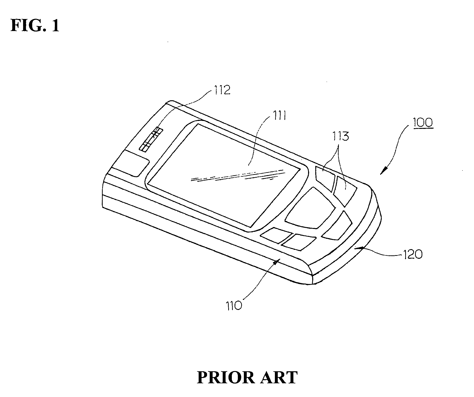
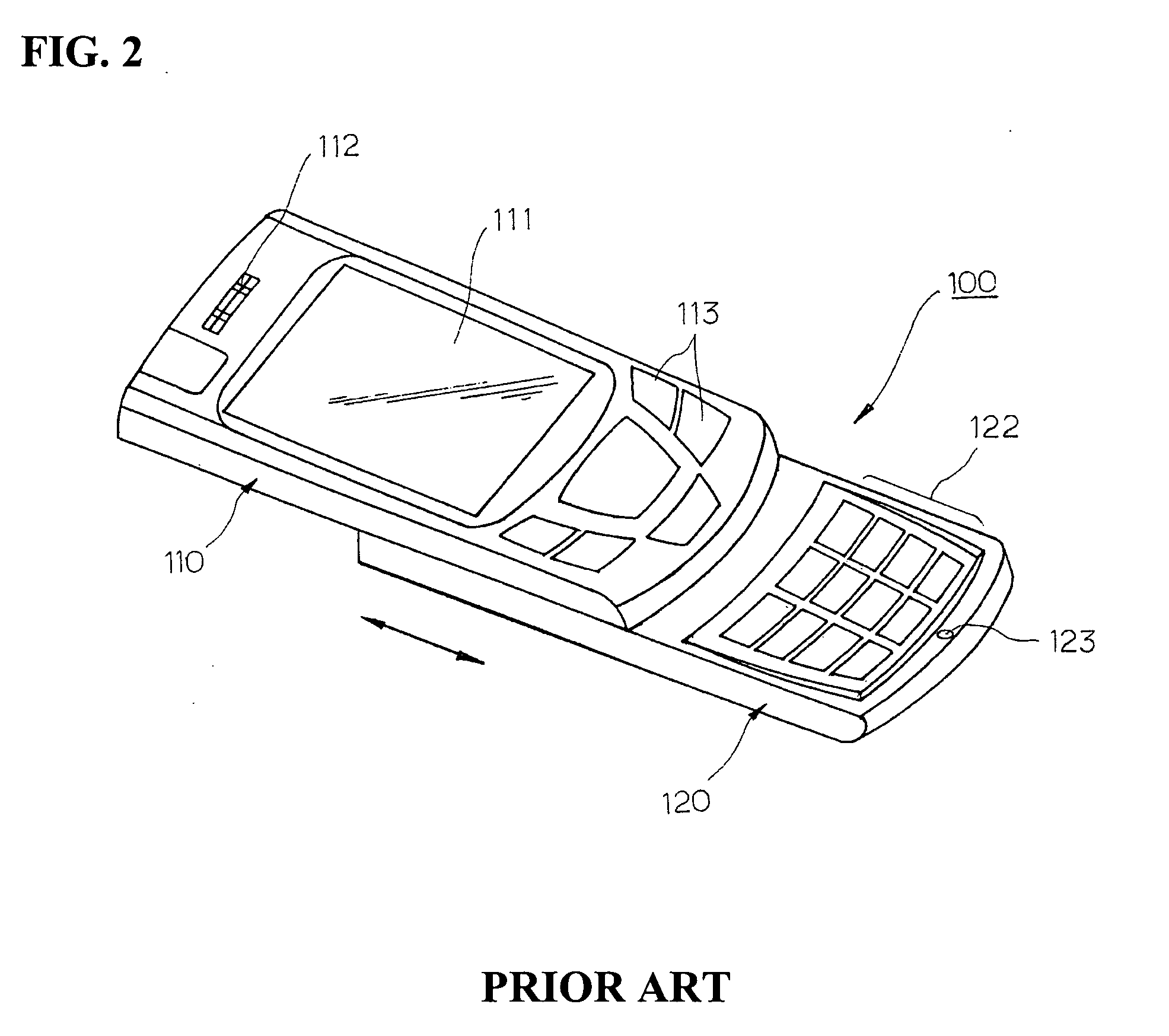
[0026]FIG. 1 is a perspective view illustrating a conventional slide type portable wireless terminal, and FIG. 2 is a perspective view illustrating a slide-up state of a conventional slide type portable wireless terminal.

[0027] As shown in FIGS. 1 and 2, the slide type portable wireless terminal 100 includes a main body 120; and a slide body 110 slidable on the main body 120 by a predetermined distance in a lengthwise direction of t...


PUM


Abstract

A built-in antenna module for a portable wireless terminal is provided. In the built-in antenna module, a mainboard, which is an RF board, has a feeding unit and a grounding unit. A radiator is disposed on one side of the mainboard and has a feed pin and a ground pin that are electrically connected to the feeding unit and the grounding unit, respectively. A conductive ground plate is disposed on the other side of the mainboard to have a predetermined height. An end of the conductive ground plate is grounded to the grounding unit of the mainboard. The distance between the radiator and the ground plate is maximized to improve antenna performance.

Description

PRIORITY [0001] This application claims priority under 35 U.S.C. § 119 to an application entitled “Built-In Antenna Module For Portable Wireless Terminal” filed in the Korean Intellectual Property Office on Sep. 17, 2004 and assigned Serial No. 2004-0074748, the contents of which are incorporated herein by reference. BACKGROUND OF THE INVENTION [0002] 1. Field of the Invention [0003] The present invention relates to an antenna module built in a portable wireless terminal, and more particularly, to a built-in antenna module for improving performance of a variety of antennas, such as improving a radiation characteristic of a Planar Inverted-F Antenna (PIFA) and reducing a Specific Absorption Rate (SAR). [0004] 2. Background of the Prior Art [0005] Recently, mobile wireless terminals, such as PCS, DCS, GPS, PDA, cellular phones and wireless notebooks, are growing in popularity; and terminals with various functions and designs are being introduced. Further, small-sized, slim and lightwe...

Claims


Application Information

Patent Timeline
Patent Type & Authority Applications(United States)
IPC IPC(8): H01Q1/24
CPCH01Q1/243H01Q1/245H01Q5/371H01Q9/0442H01Q9/0421H01Q1/24
Inventor KU, DO-ILCHOE, CHIN-SOP
Owner SAMSUNG ELECTRONICS CO LTD
Why Eureka
Try Eureka