Method and apparatus for drawing visible image on optical disk by vibrating laser beam focus

a laser beam focus and optical disk technology, applied in the direction of recording apparatus, inking apparatus, instruments, etc., can solve the problems of ineffective performance of focus servo, and inability to draw

Inactive Publication Date: 2006-03-30
YAMAHA CORP
View PDF13 Cites 8 Cited by
  • Summary
  • Abstract
  • Description
  • Claims
  • Application Information

AI Technical Summary

Benefits of technology

[0011] This invention has been made in view of the foregoing points and provides a drawing method that can perform drawing without executing a focus control and an optical disk recording apparatus for carrying out such a method.
[0013] Practically, the step of controlling increases the power of the optical beam to a level capable of forming the recording spot when the optical beam travels a region of the optical disk where the drawing is performed along a circumferential direction of the rotating optical disk, while the step of controlling deceases the power of the optical beam to another level incapable of forming the recording spot when the optical beam travels another region where the drawing is not performed along the circumferential direction of the rotating optical disk.
[0019] According to this invention, an oscillation signal is applied to a focus actuator of an optical pickup so as to cause an energy high-density portion of an optical beam (i.e., focus point of the optical beam) to recurrently pass through a target layer of an optical disk and a recording spot is formed upon occurrence of the energy high-density portion passing therethrough. Therefore, the drawing can be performed even when a focus servo cannot be effectively performed.

Problems solved by technology

However, in the method of performing the drawing on the print layer of the label side, it may occur that the focus servo is not effectively performed with respect to the print layer depending on a structure or material of the print layer, hence the drawing is disabled.
Further, also in the method of performing the drawing on the data recording layer, it may occur that the focus servo is not effectively performed with respect to the data recording layer depending on the disk so that the drawing is disabled.

Method used


Image

  • Method and apparatus for drawing visible image on optical disk by vibrating laser beam focus
  • Method and apparatus for drawing visible image on optical disk by vibrating laser beam focus
  • Method and apparatus for drawing visible image on optical disk by vibrating laser beam focus

Examples


embodiment 1

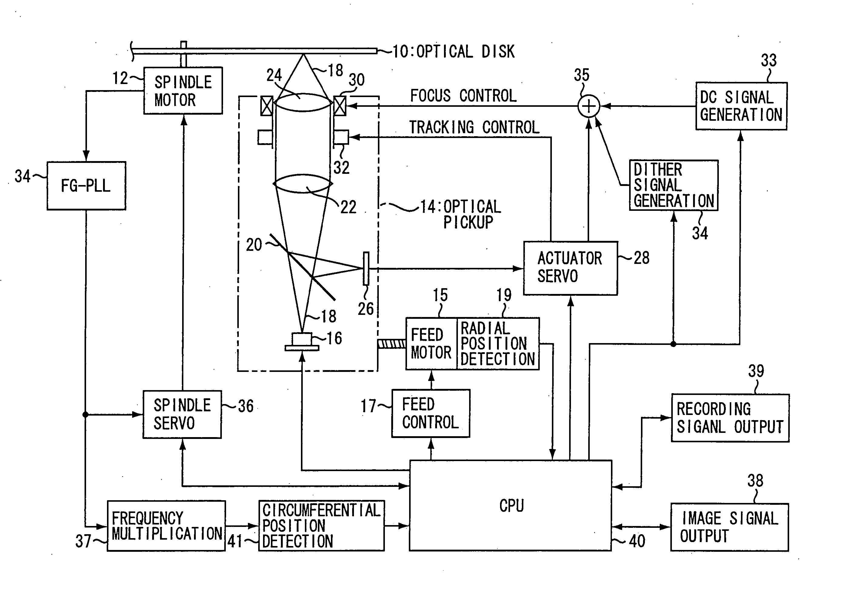
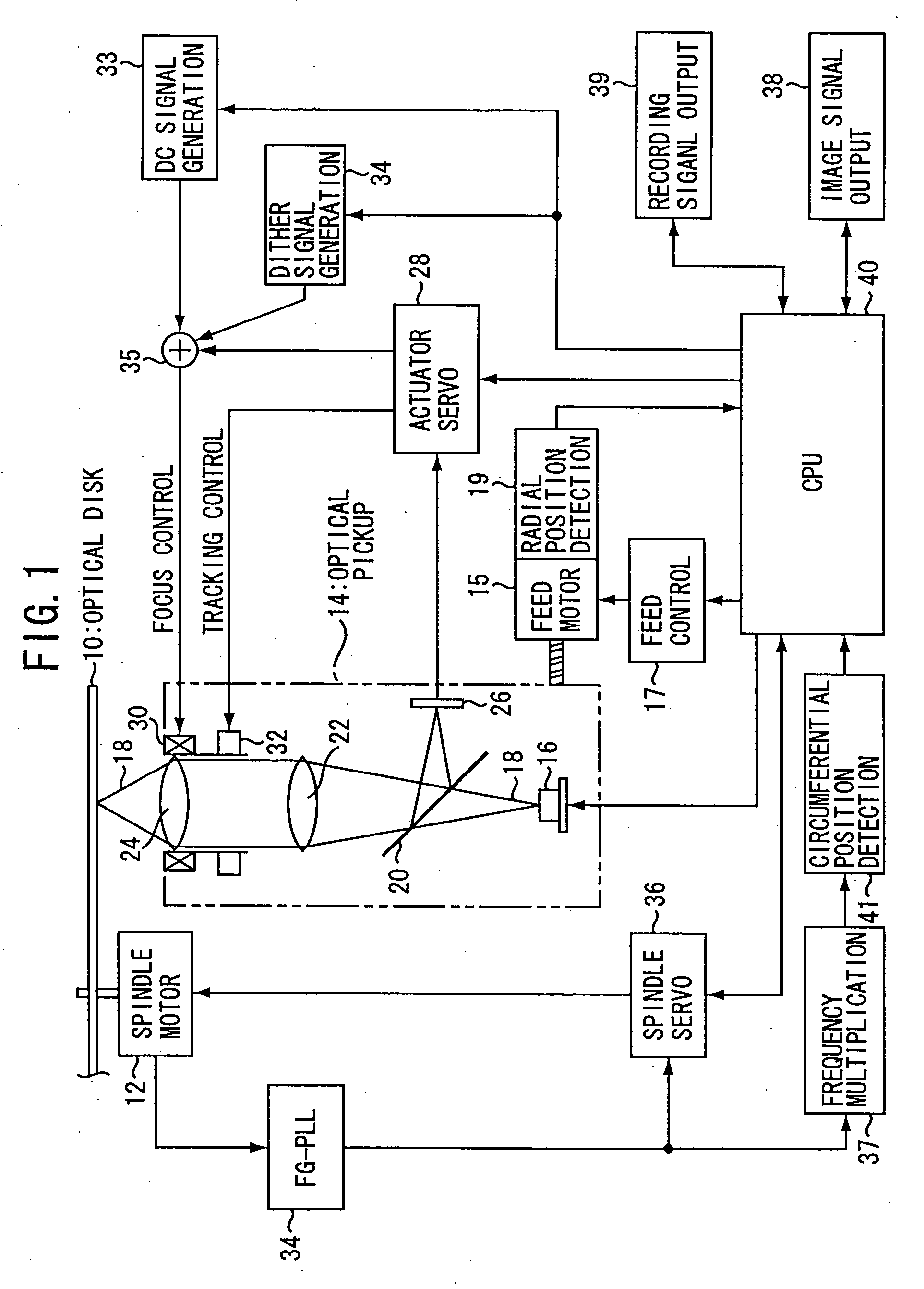
[0025] An embodiment of this invention will be described. In this embodiment, description will be given of a case where drawing is performed on a data recording layer. FIG. 1 shows an optical disk recording apparatus having a drawing function according to this invention. This optical disk recording apparatus can perform recording with respect to an optical disk, such as a CD-R, CD-RW, DVD-R, DVD+RW, DVD-RW, or DVD-RAM, whose visible light properties change by the recording and, in addition to normal information recording and reproduction, the apparatus can perform drawing according to this invention. An optical disk 10 is the foregoing type that changes in visible light properties by the recording. The optical disk 10 is mounted on a turntable with its label side facing upward, i.e. mounted with its recording side facing an optical pickup 14, rotationally driven by a spindle motor 12, and subjected to information recording, reproduction, or drawing by the use of the optical pickup 1...

embodiment 2

[0039] Another embodiment of this invention will be described. In this embodiment, drawing is performed on a data recording layer by vibrating an objective lens while making it roughly follow face runout of an optical disk. As a structure of an optical disk recording apparatus, it can be configured such that there is added in FIG. 1, instead of the DC signal generating circuit 33, a device (face runout following signal generating device) that generates a signal (face runout following signal) roughly following the face runout of the optical disk. As the face runout following signal generating device, use can be made of, for example, a device that measures, at a position where a laser beam 18 is irradiated onto an optical disk 10, an amount of displacement of the disk surface in an optical-axis direction of the laser beam 18 by the use of an optical technique, a mechanical technique, or the like. Controls at the time of normal data recording and at the time of normal data reproduction...

embodiment 3

[0041] Still another embodiment of this invention will be described. In this embodiment, an image of an optional picture or character or the like is drawn by previously forming a print layer such as a photosensitive layer or a heat-sensitive layer on a label side of a recordable optical disk and by irradiating a laser beam onto the label side of the disk to thereby change visible light properties of the print layer. At the time of drawing, an optical disk 10 is mounted upside down (i.e. with its label side facing the optical pickup 14) on the turntable. As a structure of an optical disk recording apparatus, the structure of FIG. 1 can be used. A print layer is formed over the whole surface on the label side of the optical disk 10. When a laser beam of a predetermined or more power is irradiated from the label side, the print layer changes in visible light properties {color (hue, brightness, saturation), spectrum, reflectance, transmittance, light scattering, etc.} from the label sid...


PUM

PropertyMeasurementUnit
poweraaaaaaaaaa
photosensitiveaaaaaaaaaa
heat-sensitiveaaaaaaaaaa

Abstract

A method is designed for drawing a visible image on an optical disk recordable by means of an optical pickup which irradiates an optical beam onto the optical disk through an objective lens of the optical pickup. The method is carried out by the steps pf rotating the optical disk having a target layer on which the drawing is to be performed, applying an oscillation signal to a focus actuator of the optical pickup to thereby vibrate the objective lens in an optical-axis direction thereof so that a focus point of the optical beam recurrently passes through the target layer of the optical disk, and controlling a power of the optical beam to form a recording spot on the target layer each time the focus point of the optical beam passes through the target layer so that a visible light property of the target layer is changed to thereby perform the drawing on the target layer.

Description

BACKGROUND OF THE INVENTION [0001] 1. Technical Field [0002] This invention relates to a method of performing drawing on a target layer (a data recording layer, a print layer such as a photosensitive layer or a heat-sensitive layer provided on a label side, or the like) of a recordable optical disk and an optical disk recording apparatus for carrying out such a method. [0003] 2. Background Art [0004] As a technique of drawing an image of an optional picture or character or the like by irradiating a laser beam onto a data recording layer of a recordable optical disk to thereby change visible light properties of the data recording layer, there is one method as described in, for example, the following patent document 1. [0005] As a technique of drawing an image of an optional picture or character or the like by forming a print layer such as a photosensitive layer or a heat-sensitive layer on a label side of a recordable optical disk and irradiating a laser beam onto the label side of t...

Claims


Application Information

Patent Timeline
Patent Type & Authority Applications(United States)
IPC IPC(8): G11B7/00B41J2/435
CPCG11B7/0908G11B7/0037
Inventor HAYASHI, TOYOFUMI
Owner YAMAHA CORP
Why Eureka
Try Eureka