Ophthalmic lenses incorporating a diffractive element

a diffractive element and lens technology, applied in the field of ophthalmic lenses, can solve the problem that conventional ophthalmic lenses do not adequately address problems

Inactive Publication Date: 2006-03-30
E VISION LLC
View PDF46 Cites 208 Cited by
  • Summary
  • Abstract
  • Description
  • Claims
  • Application Information

AI Technical Summary

Problems solved by technology

Conventional ophthalmic lenses do not adequately address the problems associated with presbyopia.

Method used


Image

  • Ophthalmic lenses incorporating a diffractive element
  • Ophthalmic lenses incorporating a diffractive element
  • Ophthalmic lenses incorporating a diffractive element

Examples


Embodiment Construction

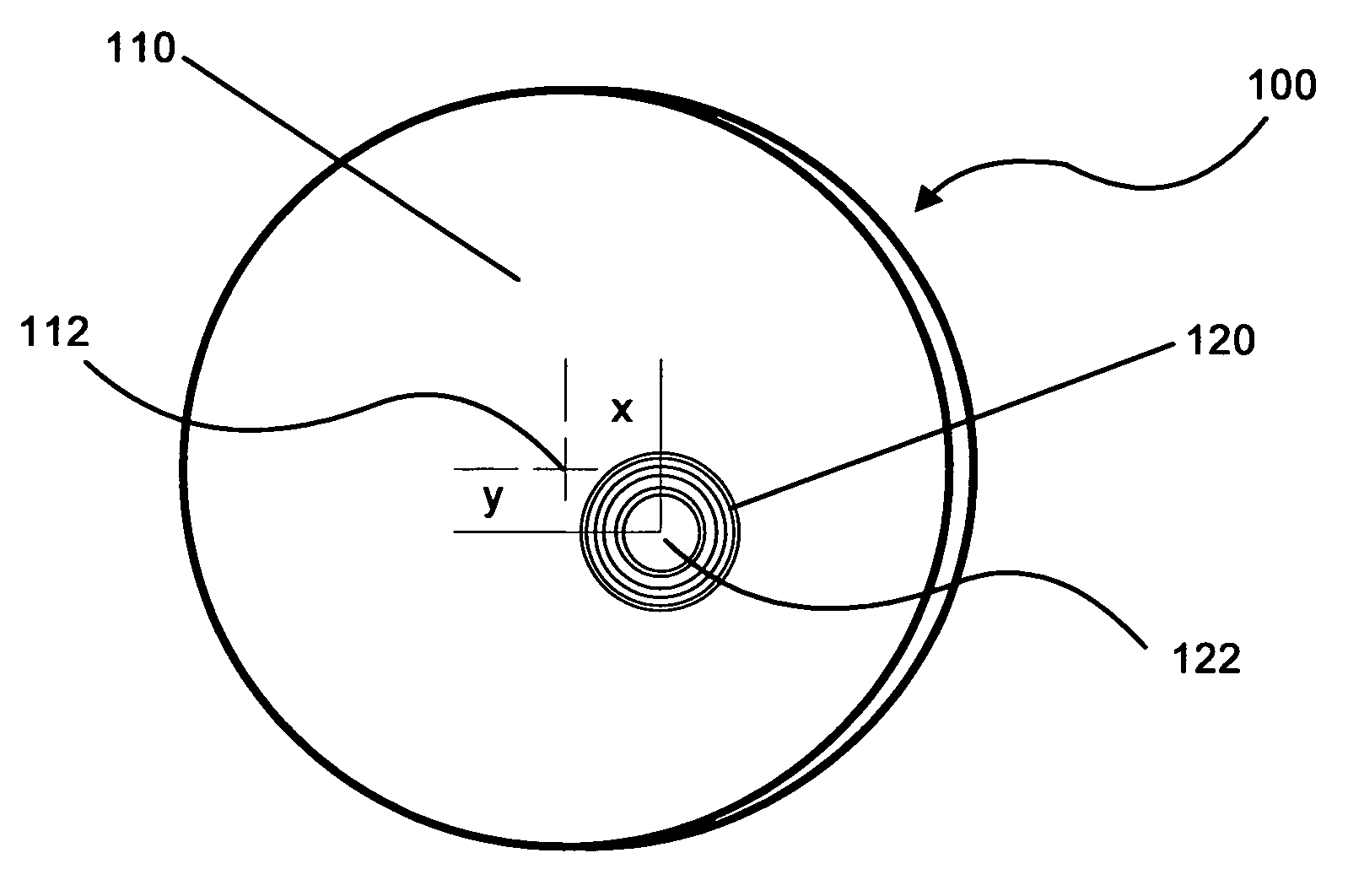
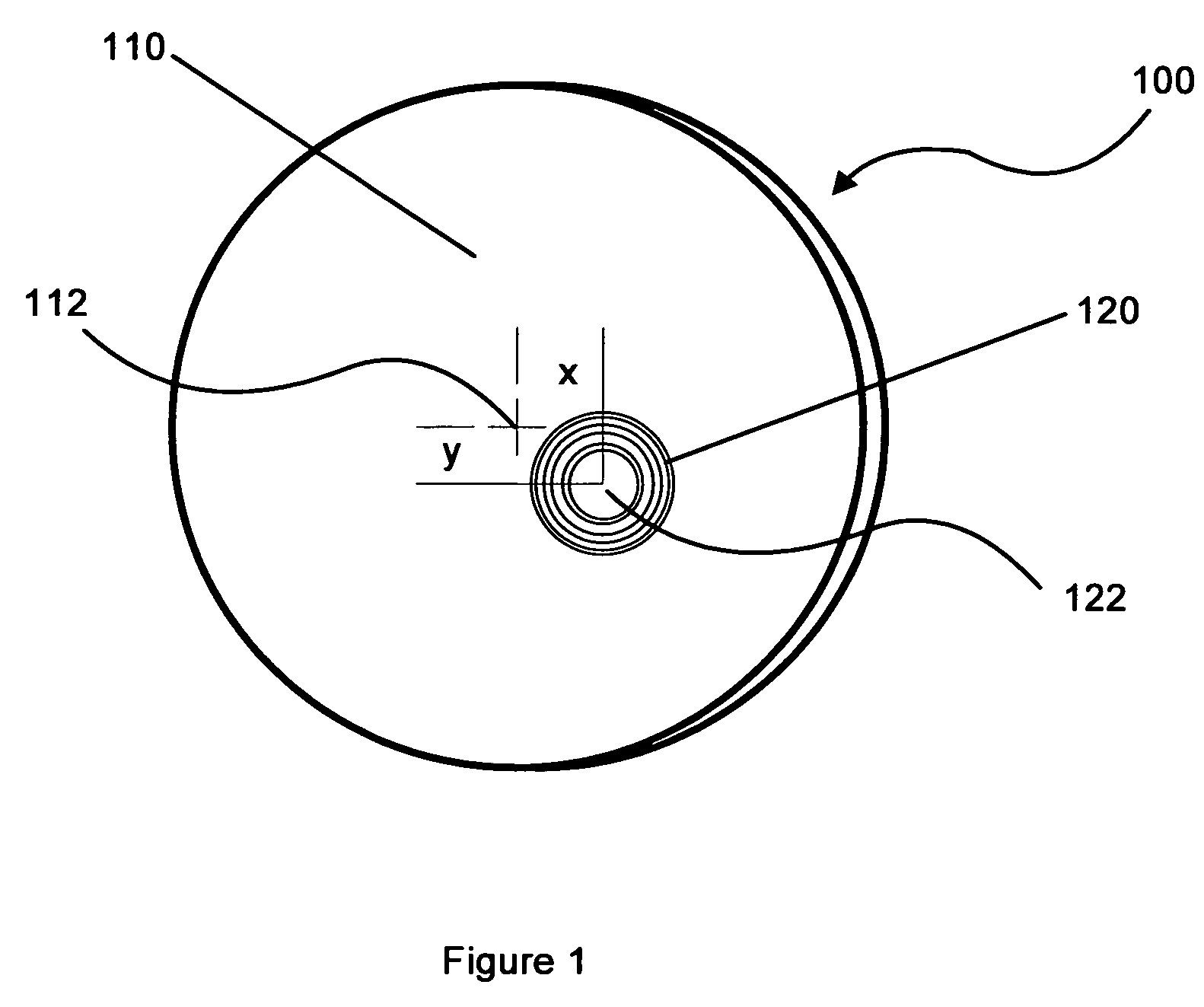
[0020] The present invention provides ophthalmic lenses that make use of diffractive elements to provide a broader range of depth of focus than would be provided by conventional lenses. As used herein, the term “ophthalmic lens” is intended to encompass any lens used for vision enhancement or correction including lenses having one or more optical elements or regions including refractive, diffractive, progressive addition, multi-focal, and electro-active elements or regions.

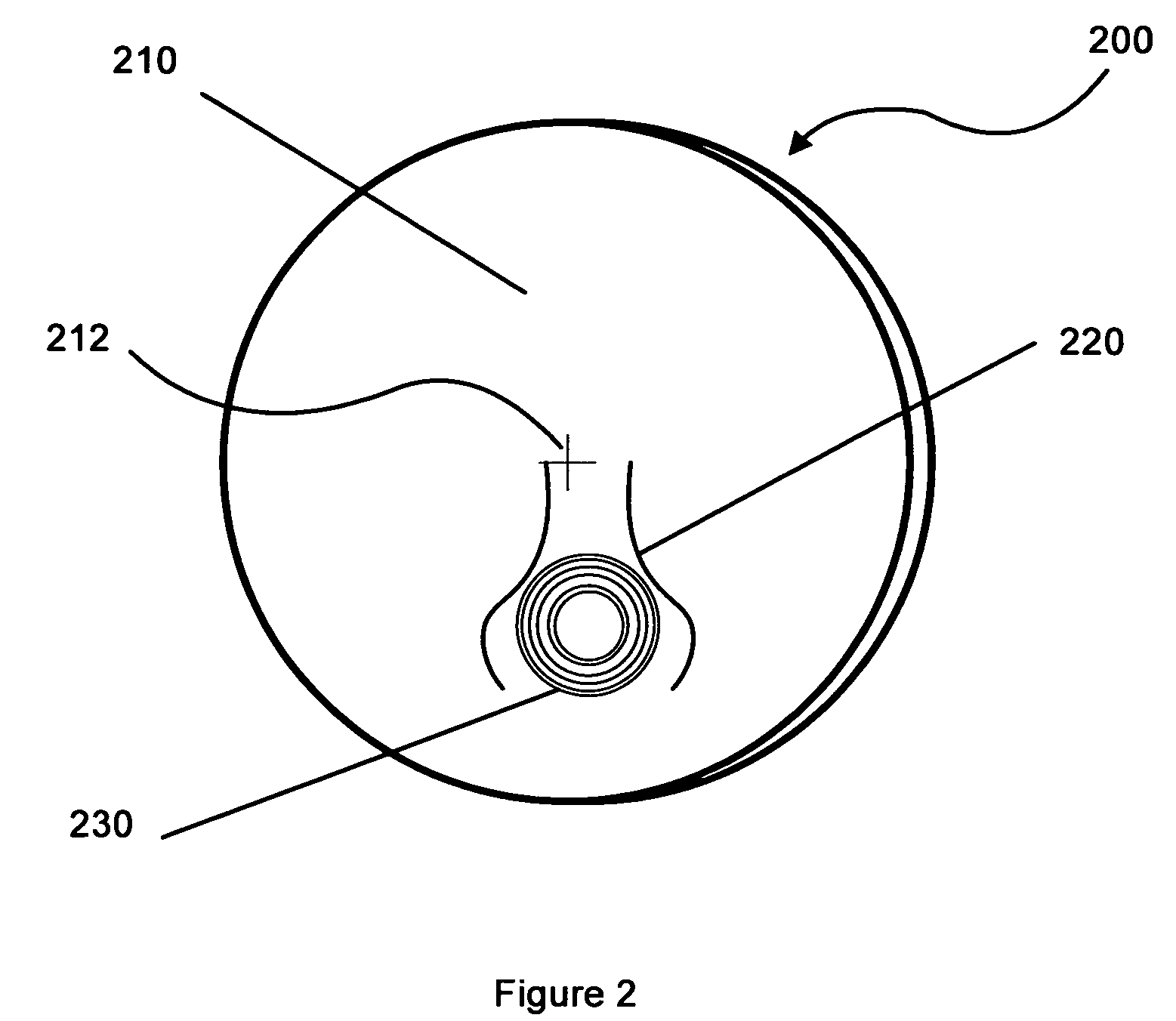
[0021] The diffractive elements used in the lenses of the invention may be combined in various embodiments to provide a variety of advantageous characteristics. In some embodiments, diffractive elements are placed on an ophthalmic lens in such a way that the wearer can selectively increase his depth of focus by directing his gaze through the region of the lens where the diffractive element is located. In some of these embodiments, the diffractive element may be co-located with other lens features such as a progre...


PUM


Abstract

An ophthalmic lens is provided that comprises a correction lens having a first focal region having a first focal power and a second focal region having a second focal power different from the first focal power. The ophthalmic lens further comprises a diffractive element having a diffractive element focal power that is additive to the second focal power. In some embodiments, the second focal region is a multi-focal region that may be a progressive addition region or an electro-active region.

Description

[0001] This application claims priority to provisional application 60 / 612,776 filed Oct. 27, 2004, and to U.S. patent application Ser. No. 10 / 627,828 filed Jul. 25, 2003, which is a continuation of U.S. patent application Ser. No. 09 / 602,013 filed Jun. 23, 2000, now U.S. Pat. No. 6,619,799, which claims priority to the following U.S. Provisional Patent Applications: [0002] Ser. No. 60 / 142,053, titled “Electro-Active Spectacles”, filed 2 Jul. 1999; [0003] Ser. No. 60 / 143,626, titled “Electro-Active Spectacles”, filed 14 Jul. 1999; [0004] Ser. No. 60 / 147,813, titled “Electro-Active Refraction, Dispensing, & Eyewear”, filed 10 Aug. 1999; [0005] Ser. No. 60 / 150,545, titled “Advanced Electro-Active Spectacles”, filed 25 Aug. 1999; [0006] Ser. No. 60 / 150,564, titled “Electro-Active Refraction, Dispensing, & Eyewear”, filed 25 Aug. 1999; and [0007] Ser. No. 60 / 161,363, titled “Comprehensive Electro-Active Refraction, Dispensing, & Eyewear” filed 26 Oct. 1999; all of which are incorporated...

Claims


Application Information

Patent Timeline
Patent Type & Authority Applications(United States)
IPC IPC(8): G02C7/02
CPCG02C7/061G02C2202/20G02C7/083
Inventor BLUM, RONALD D.KOKONASKI, WILLIAMDUSTON, DWIGHT P.
Owner E VISION LLC
Why Eureka
Try Eureka