Flexible cable for high-speed interconnect

Inactive Publication Date: 2006-03-30
INTEL CORP
View PDF8 Cites 105 Cited by
  • Summary
  • Abstract
  • Description
  • Claims
  • Application Information

AI Technical Summary

Problems solved by technology

Electrical signals, however, do not always follow the intended path.
Thus, while the signal may follow the path of the trace, there may be some loss due to the changing dielectric constant of the underlying PCB.
For very high-speed signals, the loss may be unmanageable.
As the signal passes between the motherboard and the daughtercard, loss may occur because the two boards are not impedance-matched with each other, or because the connecto

Method used


Image

  • Flexible cable for high-speed interconnect
  • Flexible cable for high-speed interconnect
  • Flexible cable for high-speed interconnect

Examples


Embodiment Construction

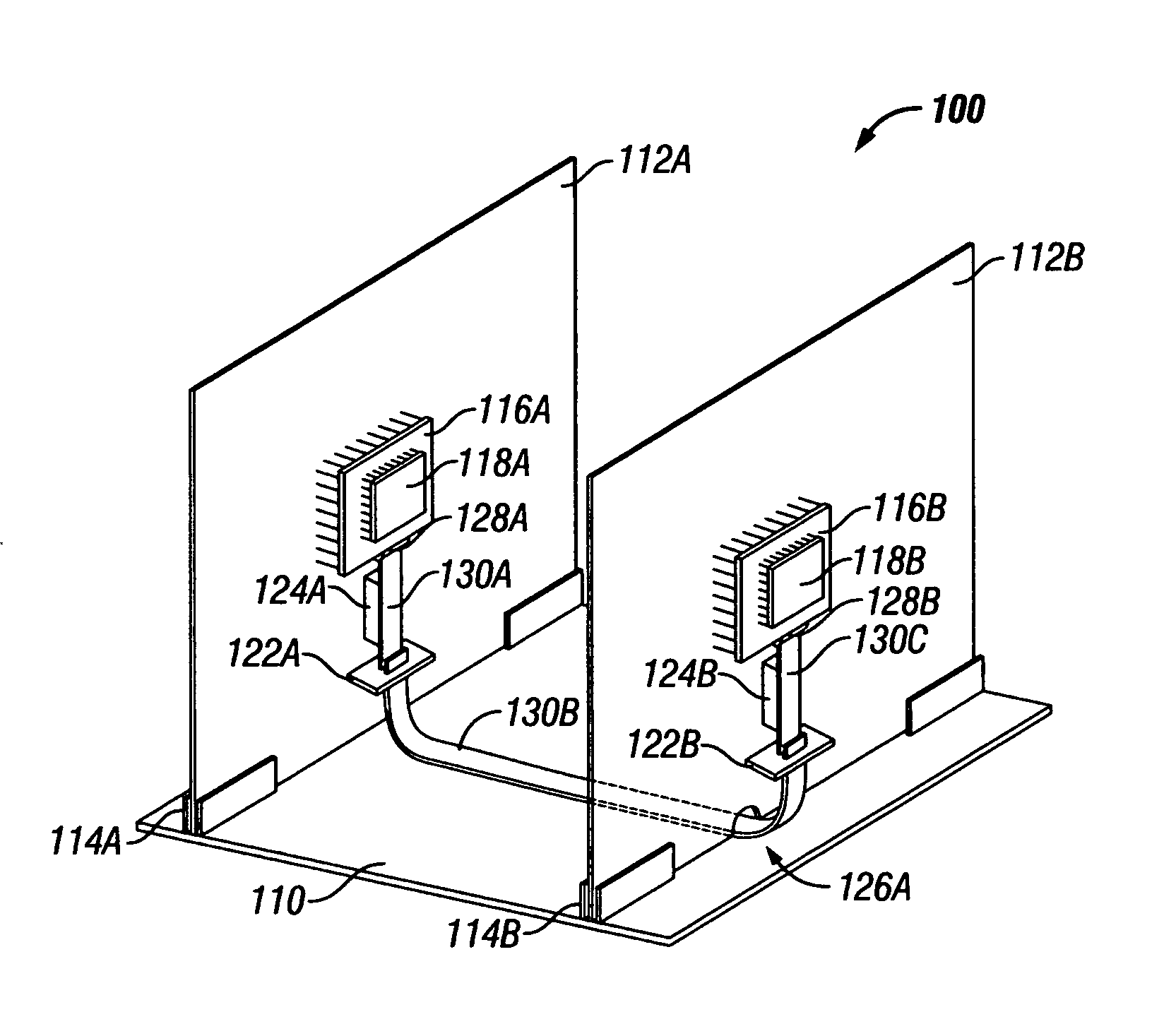
[0017] In accordance with the embodiments described herein, a system and method are disclosed in which flex cables are affixed to PCBs, for providing high-speed signaling paths between ICs disposed upon the PCBs. The flex cables are fixably attached to the PCBs so as to substantially mimic their structural orientation. Where the configuration includes more than one PCB, the flex cables include multiple portions which are temporarily separable from one another and from the die, using flex-to-flex and flex-to-package connectors, allowing field maintenance of the configuration. By routing the high-speed signals between ICs onto the flex cable, single-layer PCBs can be used for non-critical and power delivery signals, at substantial cost savings. By disposing the flex cables onto the PCB rather than allowing the cables to float freely, the configuration allows thermal air to flow as if the signals were on the PCB and cable routing problems are avoided.

[0018] In the following detailed d...


PUM

PropertyMeasurementUnit
Speedaaaaaaaaaa
Adhesivityaaaaaaaaaa

Abstract

A system and method are disclosed in which flex cables are affixed to PCBs, for providing high-speed signaling paths between ICs disposed upon the PCBs. The flex cables are fixably attached to the PCBs so as to substantially mimic their structural orientation. Where the configuration includes more than one PCB, the flex cables include multiple portions which are temporarily separable from one another and from the die, using flex-to-flex and flex-to-package connectors, allowing field maintenance of the configuration. By routing the high-speed signals between ICs onto the flex cable, single-layer PCBs can be used for non-critical and power delivery signals, at substantial cost savings. By disposing the flex cables onto the PCB rather than allowing the cables to float freely, the configuration is thermally managed as if the signals were on the PCB and cable routing problems are avoided.

Description

FIELD OF THE INVENTION [0001] This invention relates to interconnection issues between printed circuit boards and, more particularly, to the successful transmission of high-speed signals between integrated circuits disposed on two or more printed circuit boards. BACKGROUND OF THE INVENTION [0002] The standard for integrating chip-to-chip communication is the printed circuit board. Printed circuit boards (PCBs) are used to interconnect and assemble electronic circuits. A typical PCB includes at least a resin-based material, a reinforcement material, and a conductive foil. By etching traces between integrated circuits (ICs) disposed upon them, PCBs provide electrical conductor paths between the ICs. PCBs also provide mechanical structure for the components that make up the system. [0003] By far the most common PCB material is a fiber-reinforced glass epoxy material, known in the industry as Fire Retardant-4, or FR4. Woven fiberglass, impregnated with an epoxy resin, provides a solid, ...

Claims


Application Information

Patent Timeline
IPC IPC(8): H01R12/28H01R12/79
CPCG06F1/184Y10T29/49117G06F1/186G06F1/189H05K1/14H05K1/147H05K3/222H05K3/305H05K2201/044H05K2201/10356H05K2201/10492H05K2201/10704H05K2201/2027H01R12/79G06F1/185
Inventor MEIER, PASCAL C.H.DABRAL, SANJAY
Owner INTEL CORP
Why Eureka
Try Eureka