Transmission control device of motorcycle

Active Publication Date: 2006-03-30
HONDA MOTOR CO LTD
View PDF4 Cites 16 Cited by
  • Summary
  • Abstract
  • Description
  • Claims
  • Application Information

AI Technical Summary

Benefits of technology

[0007] The present invention has been made in view of such drawbacks, and it is an object of the present invention to provide a transmission control device of a vehicle such as a motorcycle

Problems solved by technology

However, in a technique disclosed in Patent Application No JP-A-4-12141, a means which controls the increase/decrease control of the engine output controls the ignition time in response to a throttle opening and an engine

Method used


Image

  • Transmission control device of motorcycle
  • Transmission control device of motorcycle
  • Transmission control device of motorcycle

Examples


first embodiment

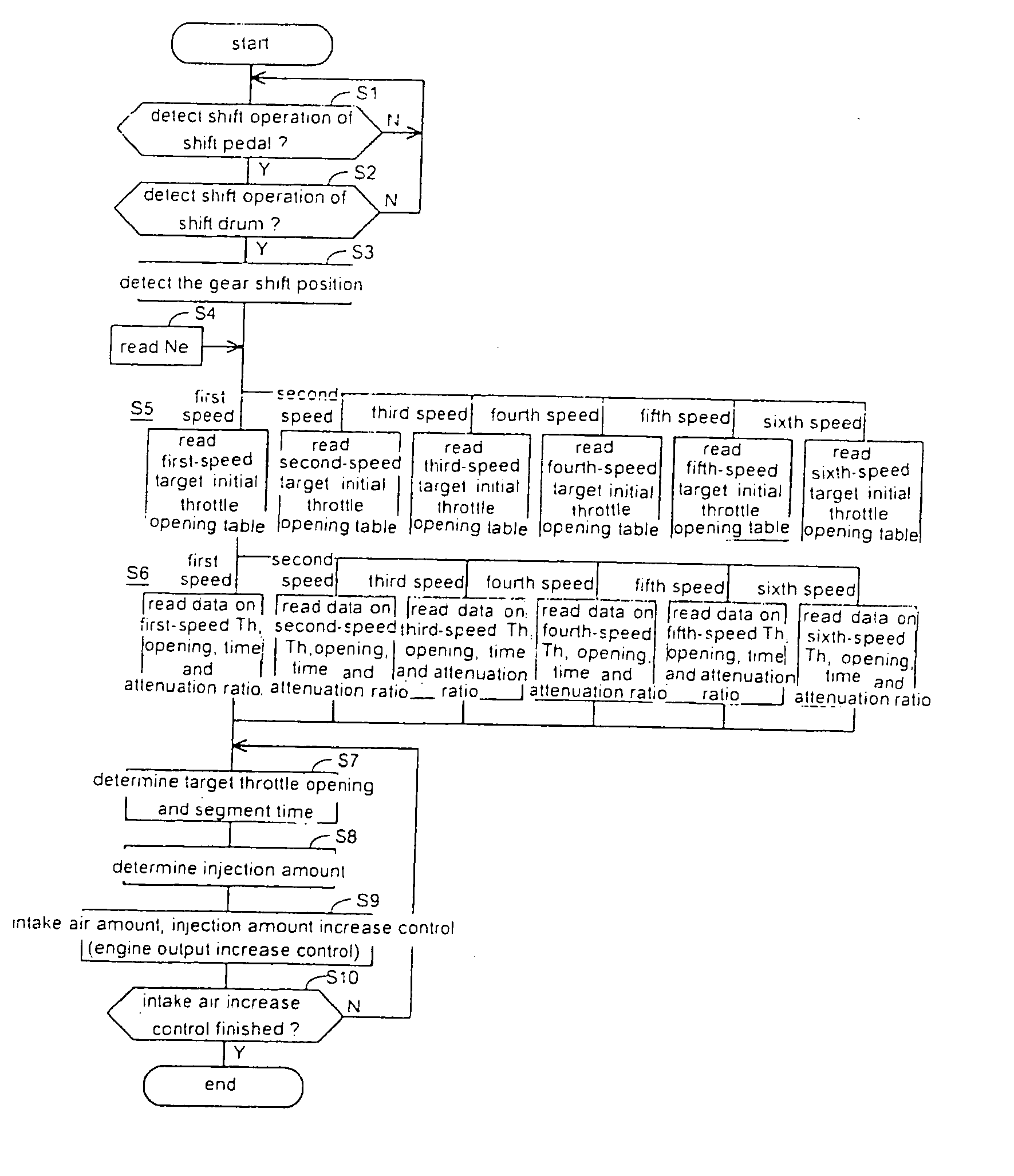
[0077] Here, the function and the manner of operation of the present invention are explained in conjunction with FIGS. 8 to 11. FIG. 8 shows a table (target initial throttle opening table) which is used to obtain a target initial throttle opening (θin) when the shift-down manipulation is performed based on the rotational speed (Ne) of the engine. The engine rotational speed is taken on an axis of abscissas and the target initial throttle openings in respective gear shift positions are taken on an axis of ordinates. From this table, it is understood that when the rotational speed of the engine is Neo, the target initial throttle opening in the third speed becomes θin3.

[0078] Next, FIG. 9 shows a data table on throttle opening, time and attenuation ratio for reducing a shock attributed to the fluctuation of the torque at the time of performing the shift-down operation as much as possible. The data table includes gear shift positions (speeds), and a first, a second . . . nth segments, ...

second embodiment

[0092] The bypass device A includes, downstream of a throttle valve Vs of the intake air passage 144, an air supply passage 148 which has one end opened and another end communicated with atmosphere by way of the air cleaner AC, an open / close valve Va which is capable of opening and closing the air supply passage 148, and a control unit 140 which is capable of performing a valve opening control of the open / close valve Va in response to information from various sensors and the like. As the control unit, a vehicle-mounted microcomputer or the like can be used. The open / close valve Va is constituted of a normally-closed electromagnetic valve in the illustrated example and performs a valve-opening operation or a valve-closing operation in response to an open / close command signal from the control unit 140. In the second embodiment, one bypass intake air supply passage 148 is provided to each cylinder of the multi-cylinder engine and the controllable open / close valve Va is provided to a mi...


PUM


Abstract

A transmission control device for a vehicle for smoothly performing a transmission manipulation without a clutch manipulation. The transmission control device includes a control unit which determines a shift operation starting time based on a detection signal of a shift operation detector, and controls an intake air amount to an engine corresponding to a gear shift position which is detected by a gear shift position detection means whereby an output of the engine is changed smoothly. For example, the control unit obtains a target initial throttle opening corresponding to the gear shift position from a target initial throttle opening table, obtains data on throttle opening, time and an attenuation ratio corresponding to the gear shift position from a throttle opening, time and attenuation ratio table, and determines the opening time and the target throttle opening. Next, the control unit determines an injection amount and executes a control to increase the intake air amount and the injection quantity.

Description

CROSS-REFERENCE TO RELATED APPLICATION [0001] The present application claims priority under 35 U.S.C. §119 to Japanese Patent Application No. 2004-260851, filed Sep. 8, 2004, the entire contents of which are hereby incorporated by reference. BACKGROUND OF THE INVENTION [0002] 1. Field of the Invention [0003] The present invention relates to a transmission control device of a motorcycle, and more particularly to a transmission control device of a motorcycle which can perform a control of an engine output in conformity with a gear shift position at the time of performing the transmission thus realizing a smooth transmission manipulation. [0004] 2. Description of Background Art [0005] Conventionally, in a vehicle such as a motorcycle, at the time of performing the transmission, a shift operation of a transmission is generally performed by rotatably manipulating a shift pedal in a state that a clutch is disengaged. On the other hand, with respect to an automobile for racing, a more rapi...

Claims


Application Information

Patent Timeline
IPC IPC(8): B60W10/04B60W10/06B60W10/10B60W10/11F02D9/02F02D29/00
CPCF02D41/0002F02D41/0225F16H59/68F16H63/502Y10T477/677Y10T477/68Y10T477/679Y10T477/675Y02T10/42Y02T10/40
Inventor KOBAYASHI, FUYUKIMUROHASHI, KOHSAKU
Owner HONDA MOTOR CO LTD
Why Eureka
Try Eureka