Systems and methods for bi-lateral guidewire cannulation of branched body lumens

a technology of branched body lumens and guidewires, applied in the field of medical devices, to achieve the effect of short length, long length, and convenient introduction of catheters

Inactive Publication Date: 2006-03-30
ANGIODYNAMICS INC
View PDF99 Cites 179 Cited by
  • Summary
  • Abstract
  • Description
  • Claims
  • Application Information

AI Technical Summary

Benefits of technology

[0014] Preferably, the systems of the present invention will further comprise an introducer sheath. The introducer sheath may have a relatively short length, typically in the range from 5 cm to 25 cm, or may have a relatively long length, typically in the range from 20 cm to 60 cm, preferably from 30 cm to 45 cm. The use of long introducer sheaths can fac

Problems solved by technology

In other cases, however, the branched ostia may not be axially aligned and/or rotationally aligned so that simultan

Method used


Image

  • Systems and methods for bi-lateral guidewire cannulation of branched body lumens
  • Systems and methods for bi-lateral guidewire cannulation of branched body lumens
  • Systems and methods for bi-lateral guidewire cannulation of branched body lumens

Examples


Embodiment Construction

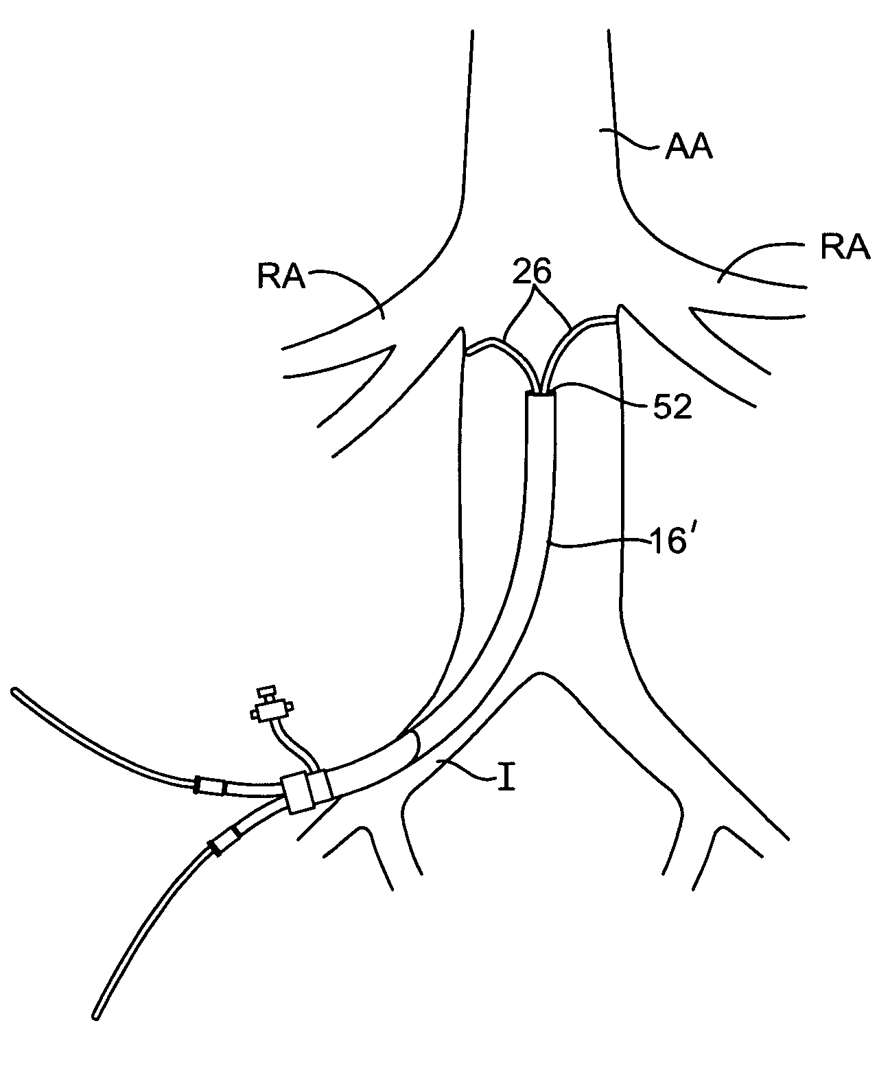
[0023] According to one present embodiment, a catheter / guidewire based system is provided that is adapted to gain rapid guidewire access to the renal arteries, such as for example for the purposes of renal diagnostic angiograms and renal intervention (e.g., percutaneous transluminal angioplasty or “PTA”, stent placement, etc.). These wires are then in place to allow catheters and other catheter type tools to be advanced over them, such as for example after a dual lumen deployment catheter is removed from the blood vessels or other body lumens, as will be explained in further detail below.

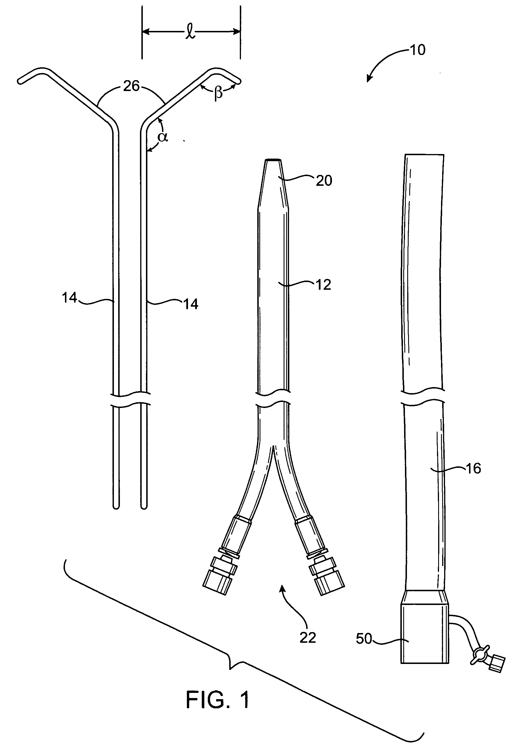
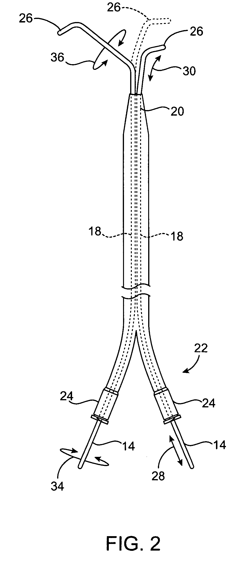
[0024] In a further detailed embodiment, systems of the present invention include the deployment catheter and a pair of pre-shaped guidewires (for example typically between about 0.014″ and 0.038″ in diameter). These guidewires are held in general spatial relationship together via the dual lumen deployment catheter. The dual lumen deployment catheter is used to keep the two individual shaped wires ...


PUM


Abstract

A system and method is provided that is adapted to allow for rapid cannulation of a guidewire into a branch lumen extending from a main lumen in a body of a patient, and in particular into two renal arteries extending from an abdominal aorta wall. A dual lumen catheter shaft delivers first and second pre-shaped guidewires to the location of the renal arteries in the aorta, such that the first and second pre-shaped guidewires self-cannulate within the renal arteries. Additional guidewires and/or interventional devices may be incorporated into the system and method for use with the catheter shaft, or over the two pre-shaped guidewires, to meet a particular need for a particular patient or intended procedure.

Description

CROSS-REFERENCES TO RELATED APPLICATIONS [0001] This application claims the benefit of prior provisional patent application No. 60 / 612,801 (Attorney Docket No. 022352-002700US), filed on Sep. 24, 2004, the full disclosure of which is incorporated herein by reference. [0002] This application is related to but does not claim priority from the following international applications which are incorporated herein by reference in their entirety: PCT / US01 / 13686 published as WO2001 / 83016A2; PCT / US03 / 21406; PCT / US03 / 29740 published as WO2004 / 026370A3; PCT / US04 / 08571; PCT / US03 / 29744 published as WO2004 / 032791A3; PCT / US03 / 29995 published as WO2004 / 030718A3; PCT / US03 / 29743 published as WO2004 / 026371A2; PCT / US03 / 29585 published as WO2004 / 034767A2; PCT / US03 / 29586; and PCT / US04 / 08573. This application is also related to but does not claim priority from the following U.S. applications which are incorporated herein by reference in their entirety: Ser. No. 09 / 229,390; Ser. No. 09 / 562,493; Ser. No. 09 / 7...

Claims


Application Information

Patent Timeline
IPC IPC(8): A61M25/00
CPCA61M25/01A61M25/0105A61M25/09A61M25/0662A61M25/0172
Inventor ELKINS, JEFFREY M.GOODSON, HARRY B. IVVALENCIA, AURELIOABOYTES, RICHARDPATEL, SAMIR
Owner ANGIODYNAMICS INC
Why Eureka
Try Eureka