
Multi-stage turbocharging system utilizing VTG turbine stage(s)

a turbocharger and multi-stage technology, applied in the direction of charge feed system, non-fuel substance addition to fuel, combustion engine, etc., can solve the problems of turbocharger performance decline, turbocharger has a tendency to “overspeed”, and loss of efficiency, etc., to achieve significant benefits

Inactive Publication Date: 2006-04-06
BORGWARNER INC
View PDF18 Cites 93 Cited by
  • Summary
  • Abstract
  • Description
  • Claims
  • Application Information

AI Technical Summary

Benefits of technology

[0027] Following extensive theoretical discussions, followed by laboratory prototyping and road testing of various turbocharger systems, the present inventors discovered that, among the hundreds of possible modifications and combinations that may be made to multi-stage turbocharger systems, a few certain specific modifications or adjustments resulted in improved fuel economy and reduced emissions while at the same time improving engine responsiveness.

Problems solved by technology

However, when operated over a broad range of engine speed and load, the compressor and turbine components are forced to function off their design points and consequently suffer losses in efficiency that adversely affects engine performance.
Conversely, if the turbocharger is matched to an engine's low speed range, the turbocharger will have a tendency to “overspeed” when the engine is operated at maximum speed and load.
The waste gate, however, allows the escape of exhaust gas energy which could be better utilized by the turbocharger turbine, and results in a substantial loss in system efficiency.
However, the increase in boost at low engine speeds produced by the diverted flapper valve might be great enough to cause the turbocharger compressor to operate in its surge or unstable area.
This in turn causes a movement of the compressor efficiency islands and choke area to lower flow and can result in lowering the compressor efficiency when the engine is operating at high speed and load.
Variable diffuser vanes is one type of variable geometry compressor that could be employed, but the movable vanes cause significant mechanical complication internally in the construction of the turbocharger and must be precisely positioned by a rather elaborate control system.
The developers of new turbocharging systems are therefore faced with a dilemma: achieving a further rise in the rated power of an engine would require the use of a relatively large turbocharger.
While being simple, this two-stage turbocharger system does not produce the combination of performance and emissions characteristics required of modern propulsion systems.
Consequently, there may be a loss of traveling comfort, i.e. unsteady acceleration and braking power response.
There is thus need for an uncomplicated system able to improve low engine RPM boost / torque, particularly in medium size trucks.

Method used


Image

  • Multi-stage turbocharging system utilizing VTG turbine stage(s)
  • Multi-stage turbocharging system utilizing VTG turbine stage(s)
  • Multi-stage turbocharging system utilizing VTG turbine stage(s)

Examples


first embodiment

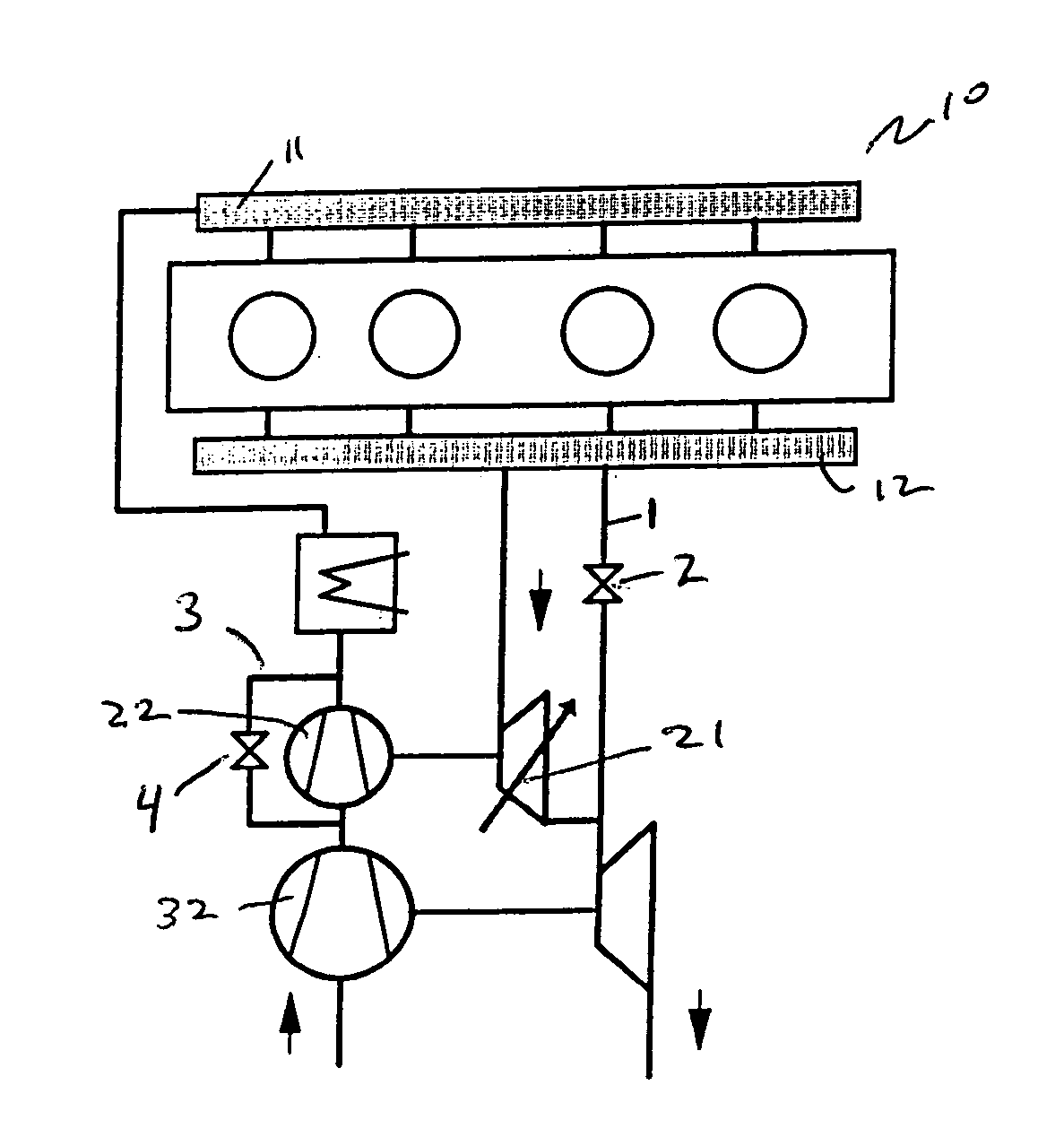
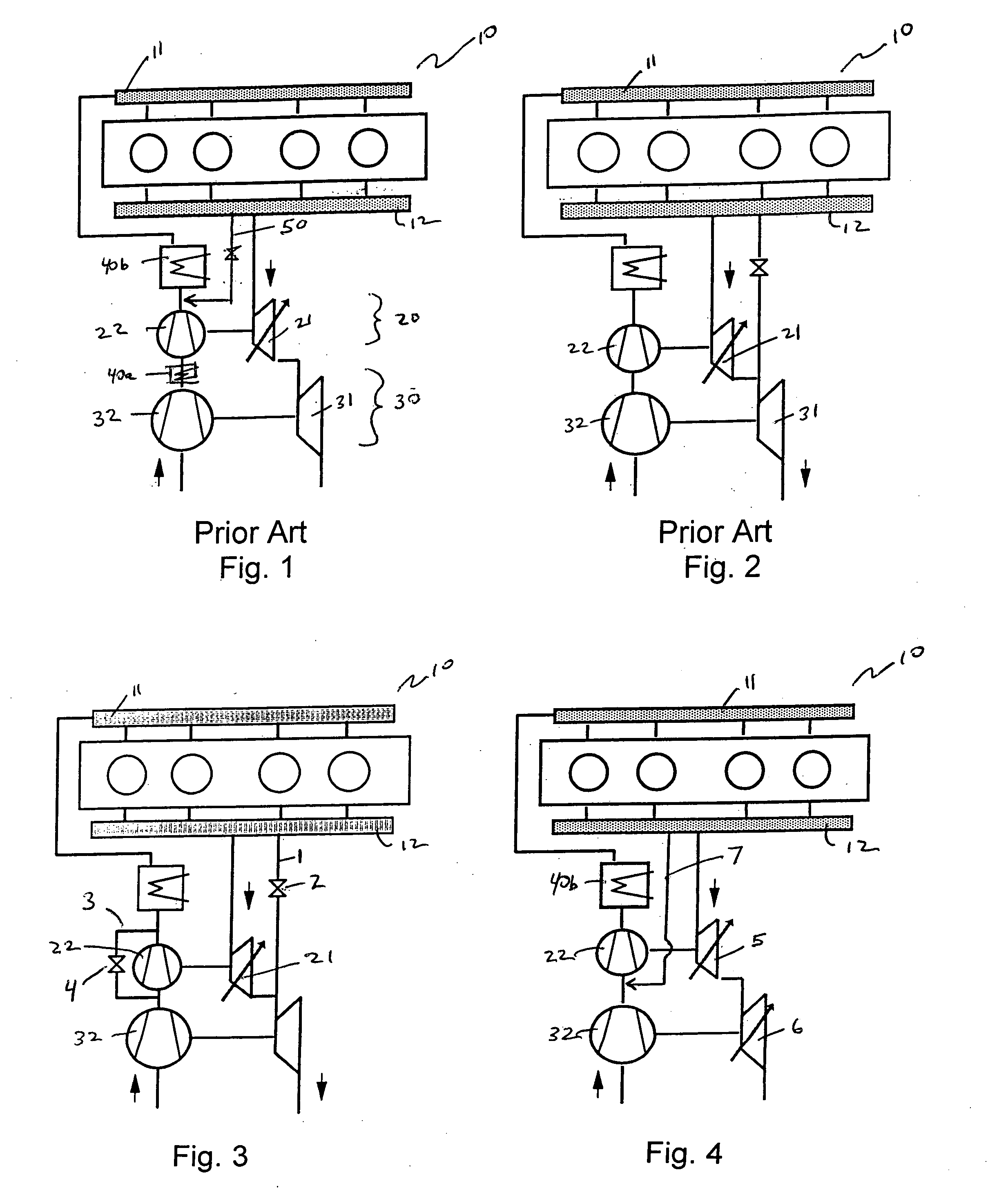
[0059] Turning now to the present invention, according to the invention as shown in FIG. 3, the inventors discovered that significant benefits could be obtained by providing the variable regulated two stage turbocharger (VR2S) shown in FIG. 2 with a HP compressor bypass (hereafter VR2S-CB) comprising bypass pipe 3 and pipe switch 4. More complex than the VR2S, this design allows both the HP turbine and the HP compressor to be bypassed, such that the system could in effect, at high exhaust gas flow low power (e.g., maintaining high speed on a level highway), simply operate as an efficient single stage compressor, with large LP turbine and large LP compressor. The HP compressor, being bypassed, does not impede flow of air from the LP compressor to the engine. At the same time, since the HP stage is allowed to “idle”, it allows the HP stage to quickly increase RPM, thus provide rapid transient response, when acceleration is required for passing or when power is required for climbing.

[0...

fourth embodiment

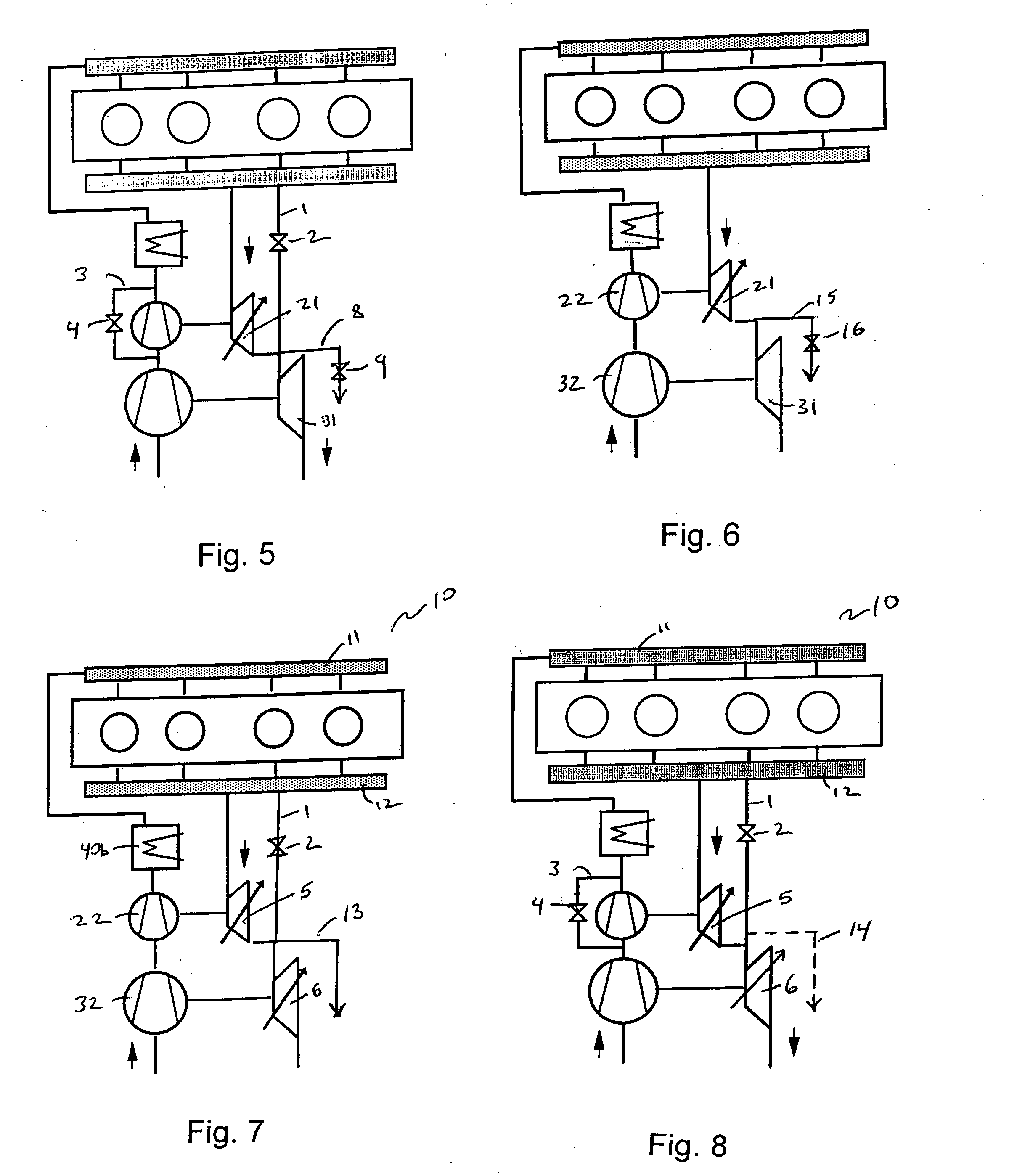
[0062] According to the invention, the inventors discovered that significant benefits could be obtained by providing a V2S with a LP turbine bypass pipe 15 and pipe switch 16 (hereafter V2S-LTB).

fifth embodiment

[0063] According to the invention, the inventors discovered that significant benefits could be obtained by providing a DV2S with a HP turbine bypass pipe 1 and switch 2 (thus making the system “regulated”) and with a LP turbine bypass 13 (hereafter DVR2S-LTB).


PUM


Abstract

Multi-stage turbocharging, and more particularly, an advanced multi-stage turbocharging system using the variable turbine power of one or more variable turbine geometry (VTG) turbochargers to adjust compressor boost and exhaust back pressure to engine operating demands. The invention further relates to a turbocharged internal combustion engine, in particular a turbocharged internal combustion engine with at least one high-pressure turbine stage and one downstream low-pressure turbine stage, wherein the high-pressure turbine may be a single-flow or double-flow type, wherein the high pressure or low pressure compressor may be variable geometry, wherein the high pressure or low pressure compressor may be variably bypassed, and wherein the high pressure or low pressure turbine may be provided with an active control variable bypass or wastegate.

Description

REFERENCE TO RELATED APPLICATION [0001] This application is a non-provisional of provisional application No. 60 / 613,615 filed Sep. 27, 2004.BACKGROUND OF THE INVENTION [0002] 1. Field of the Invention [0003] The invention relates to advanced multi-stage turbochargers using at least one variable turbine geometry (VTG) turbocharger stage to enable higher pressure ratios, better torque at low engine speed, increased power / altitude capability at high speeds, a wider operating range without running into choke or surge, improved flexibility, and improved transient capability. [0004] The invention further relates to a turbocharged internal combustion engine with at least one high-pressure turbine stage and one downstream low-pressure turbine stage, wherein the high-pressure turbine may be a single-flow or double-flow type, wherein the high pressure or low pressure turbine or compressor may be bypassed, wherein the high pressure or low pressure turbine or compressor may be variable geometry...

Claims


Application Information

Patent Timeline
Patent Type & Authority Applications(United States)
IPC IPC(8): F02B33/44F02B29/04
CPCF02B29/0412F02B37/00F02B37/001F02B37/004F02B37/013F02B37/025F02B37/16F02B37/18F02B37/22F02B37/225F02B37/24F02M25/0711Y02T10/144F02M26/08Y02T10/12
Inventor PARLOW, ERICSWEETLAND, PATRICKRICE, MATT
Owner BORGWARNER INC
Learn More