Reciprocating engine

a technology of reciprocating engine and piston, which is applied in the direction of trunk piston, cylinder, pulverizer, etc., can solve the problems of increasing the difficulty of reducing the sliding frictional resistance between the cylinder and the required amount of combustion gases in the combustion chamber, and reducing the sliding frictional resistance. , to achieve the effect of reducing the sliding frictional resistan

Inactive Publication Date: 2006-04-06
BANDO KIKO CO LTD
View PDF3 Cites 6 Cited by
  • Summary
  • Abstract
  • Description
  • Claims
  • Application Information

AI Technical Summary

Benefits of technology

[0062] According to the present invention, it is possible to provide a reciprocating engine which is capable of speedily introducing a necessary amount of gases in the combustion chamber into and causing it to act in the annular gas chamber with necessary force during a starting period of the fall of the piston in the explosion stroke and of generating a desired gas-pressure supporting force, thereby making it possible to substantially reduce the sliding frictional resistance between the cylinder, on the one hand, and the piston rings and the side surface of the piston, on the other hand.
[0063] In addition, according to the present invention, it is possible to provide a reciprocating engine which is capable of eliminating the interference of the piston ring with the oil ring and of generating the desire lateral pressure, thereby making it possible to substantially reduce the sliding frictional resistance between the cylinder, on the one hand, and the piston rings and the side surface of the piston, on the other hand.

Problems solved by technology

Therefore, a required amount of combustion gases in the combustion chamber cannot be speedily introduced into the annular gas chamber through a single gas passage.
Hence, it is difficult to substantially reduce the sliding frictional resistance between the cylinder, on the one hand, and the piston rings and the side surface of the piston, on the other hand, by generating desired supporting force.
In a case where the second piston ring is inclined greatly or in a case where the period of communication between the combustion chamber and the annular gas chamber per reciprocating motion becomes short due to the high-speed rotation of the reciprocating engine, it can become even more difficult to introduce a required amount of combustion gases in the combustion chamber speedily into the annular gas chamber.
In addition, with the above-described other reciprocating engine, if the second piston ring is inclined greatly so as to generate large lateral pressure on the thrust side, there is a possibility that the inclined second piston ring interferes with an oil ring.
Accordingly, it is difficult to substantially reduce the sliding frictional resistance between the cylinder, on the one hand, and the piston rings and the side surface of the piston by generating desired lateral pressure.

Method used


Image

  • Reciprocating engine
  • Reciprocating engine
  • Reciprocating engine

Examples


Embodiment Construction

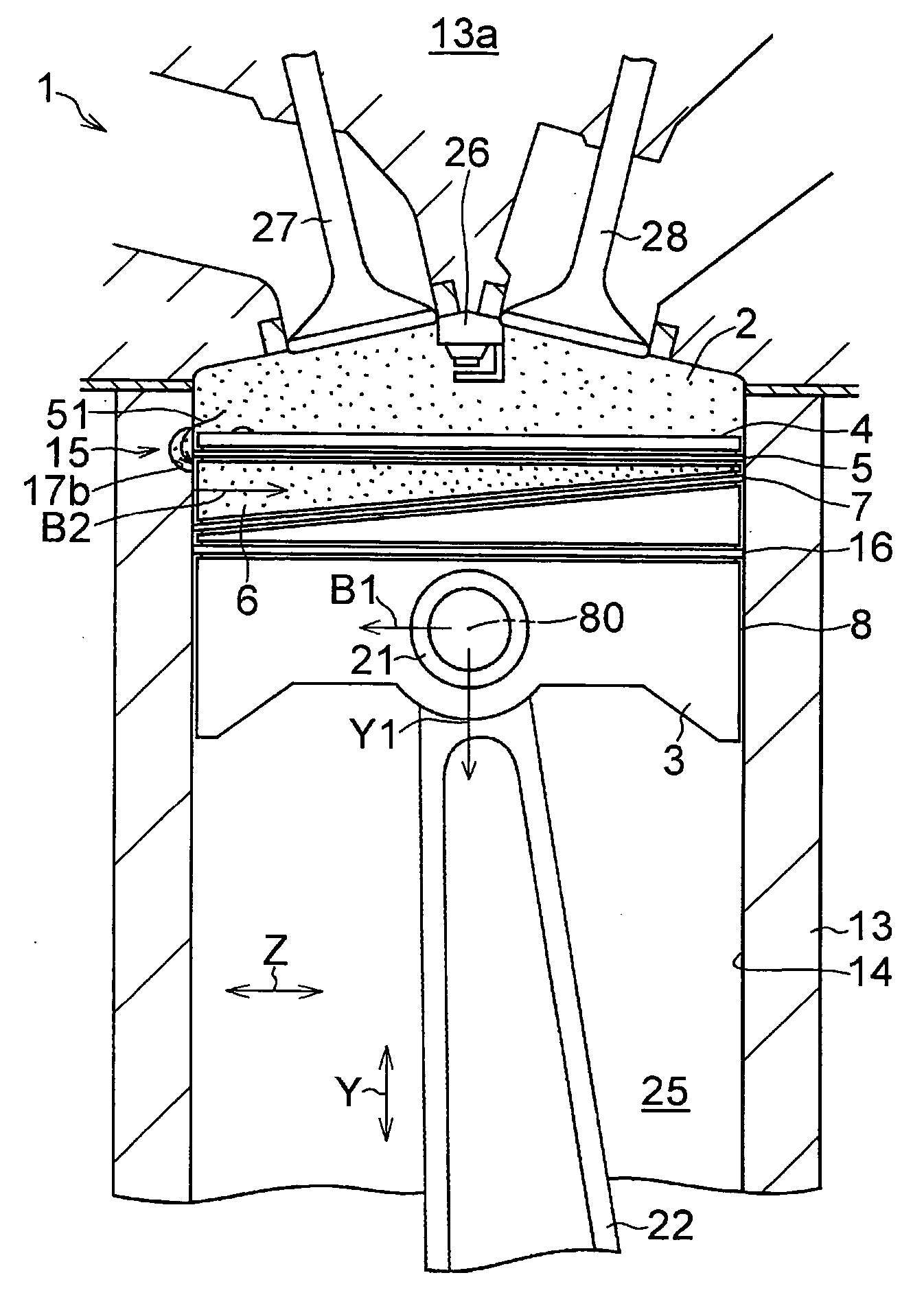
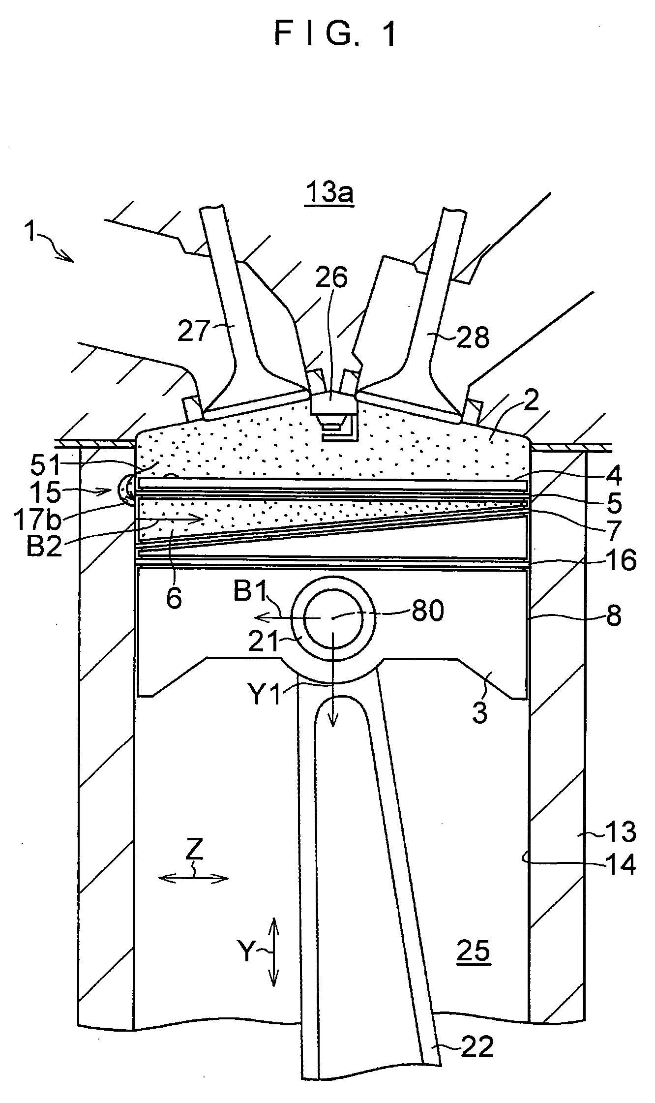
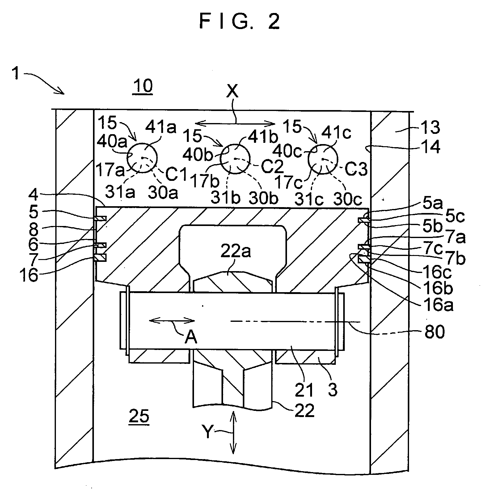
[0079] In FIGS. 1 to 8, a four-cycle gasoline engine 1 serving as a reciprocating engine in accordance with this embodiment is comprised of a piston ring (top ring) 5 adjacent to a top surface (head end face) 4 of a piston 3 defining a combustion chamber 2; a piston ring 7 which defines an annular gas chamber 6 in cooperation with the piston ring 5 and which is adjacent to the piston ring 5 such that the pressure-receiving area of a side surface 8 of the piston 3 in the annular gas chamber 6 becomes greater on a thrust side 10 than on a counter-thrust side 9 of the piston 3; a plurality of gas passages 15 which are disposed in an inner surface 14 of a cylinder 13 in such a manner as to be juxtaposed in a circumferential direction X of the inner surface 14 of the cylinder 13 and which allow the annular gas chamber 6 to communicate with the combustion chamber 2 on the thrust side 10; and an oil ring 16 disposed in such a manner as to oppose the piston ring 5 with the piston ring 7 loc...


PUM


Abstract

A reciprocating engine comprises: a piston ring; a piston ring which defines an annular gas chamber in cooperation with the piston ring and which is adjacent to the piston ring such that a pressure-receiving area of a side surface of a piston in the annular gas chamber becomes greater on a thrust side than on a counter-thrust side of the piston; and gas passages for allowing the annular gas chamber to communicate with the combustion chamber.

Description

TECHNICAL FIELD [0001] The present invention relates to a reciprocating engine for use in an automobile or the like. BACKGROUND ART [0002] As a reciprocating engine of this type, a reciprocating engine has been proposed in JP-A-5-180069 in which, in order to reduce sliding frictional resistance between a side surface of a piston and an inner surface of a cylinder which increases as a connecting rod is inclined in an explosion stroke (combustion stroke), a second piston ring (second ring) adjacent to a first piston ring (top ring) is inclined with respect to the first piston ring, and a combustion chamber and an annular gas chamber between the first and second piston rings are communicated through a gas passage. In such a reciprocating engine, the support of the piston (gas-pressure support) on the thrust side occurring on the basis of the gas pressure of the annular gas chamber is increased by tilting the second piston ring, so as to reduce the sliding frictional resistance between ...

Claims


Application Information

Patent Timeline
Patent Type & Authority Applications(United States)
IPC IPC(8): F02F3/00F02B75/06F02F1/18F16J9/00F16J9/22F16J10/02
CPCF02B75/06F02F1/18F16J9/00F16J9/22F16J10/02F02F1/00F02F3/00F02F5/00F16J1/00
Inventor BANDO, SHIGERU
Owner BANDO KIKO CO LTD
Why Eureka
Try Eureka