Fixtureless vertical paddle electroplating cell

Inactive Publication Date: 2006-04-06
CHEM SAFETY TECH
View PDF8 Cites 24 Cited by
  • Summary
  • Abstract
  • Description
  • Claims
  • Application Information

AI Technical Summary

Benefits of technology

[0009] Additional walls of the assembly may form a submersible compartment for fluid-tight submersion into the electrolyte bath and into which the work-pieces can be removably positioned. A bellows surrounds the chuck mechanism and for sealing the chuck mechanism within the compartment from any fluid which may inadvertently invade the compartment.
[0010] The retractable, bellow-sealed chuck; the wall/cathode contact with recess seal; and the overall submersible cathode

Problems solved by technology

Certain challenges exist in electroplating systems.
In addition, some systems require the use of complex fixtures to hold the work-piece in place during elec

Method used


Image

  • Fixtureless vertical paddle electroplating cell
  • Fixtureless vertical paddle electroplating cell
  • Fixtureless vertical paddle electroplating cell

Examples


Embodiment Construction

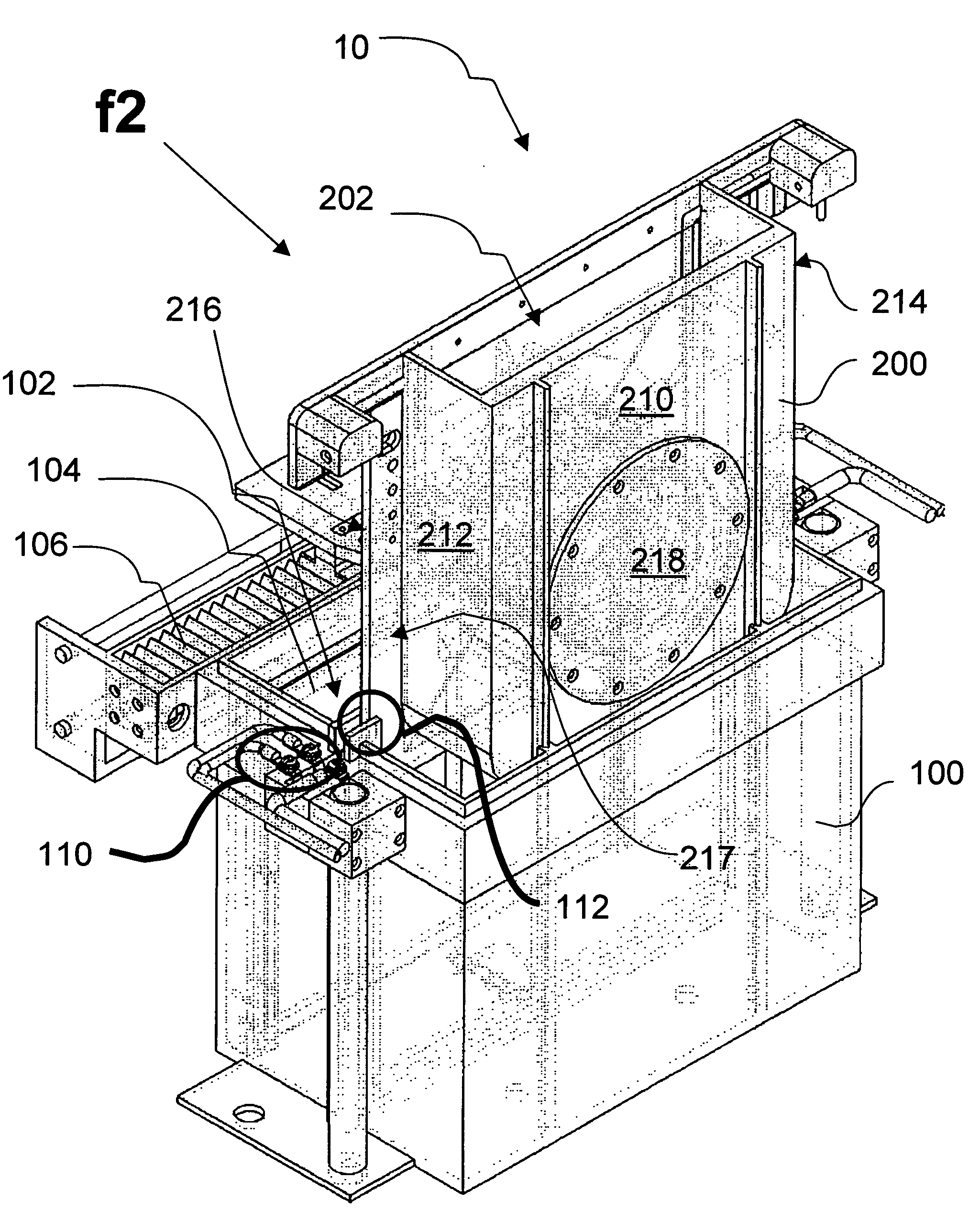
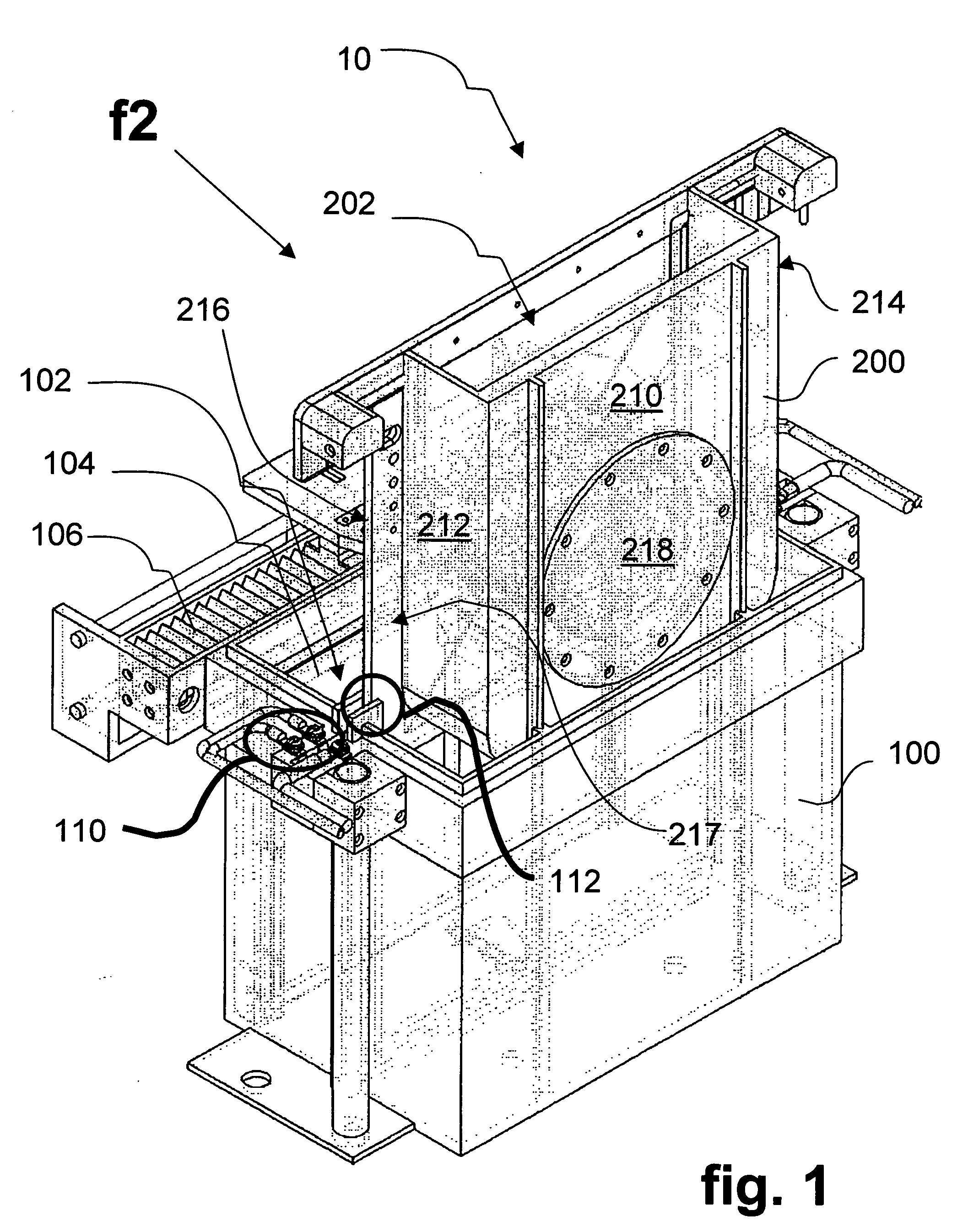
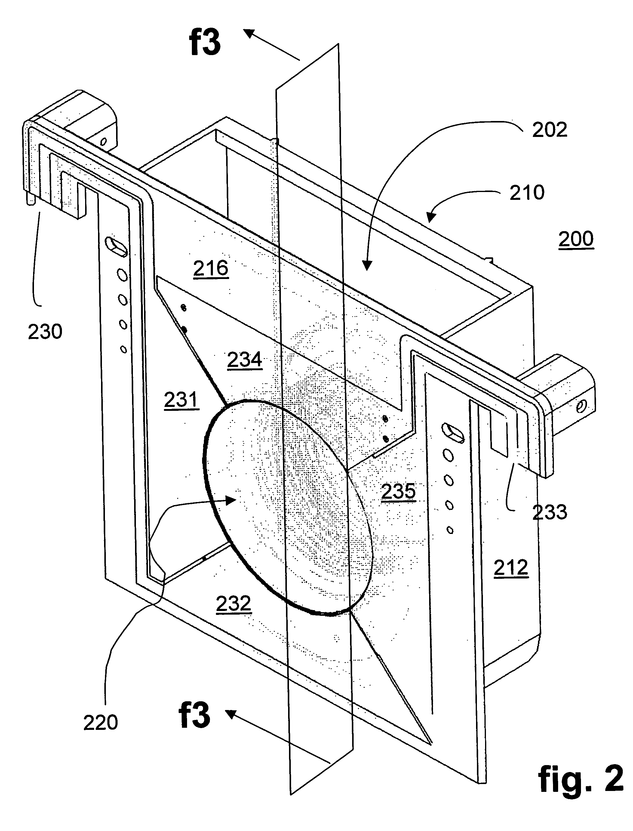
[0020] As discussed above, the present invention is directed to a fixture-less electroplating apparatus which facilitates easy insertion, positioning, and removal of a work-piece from an electroplating bath. The invention includes in one embodiment a submersible cathode compartment assembly serving as the “vehicle” for carrying the work-piece into the bath. Advantageously, the front surface of the work-piece is exposed to the bath, while the back surface of the work-piece is protected from exposure within the submersible compartment; and the technique for handling the work-piece can be implemented without any significant pre-fixturing of the work-piece, thus substantially increasing production throughput.

[0021] With reference to FIG. 1, electroplating assembly 10 includes a primary electroplating cell 100 containing the volume of electrolyte in its tank 102 and an anode 104 held in place within the tank, here vertically against one wall. The tank in one embodiment includes bottom, ...


PUM


Abstract

A submersible assembly for exposing respective front surfaces of different work-pieces to an electroplating bath as a partial respective electrodes thereof, while protecting opposing, rear surfaces of the work-pieces from the bath. The assembly includes a wall, having a front surface also partially forming a first electrode of the bath, and having an opening smaller in size than the perimeter of a work-piece while substantially corresponding in size to the portion of the front surface of the work-piece to be exposed to the bath. The assembly also includes a chuck mechanism for applying pressure against the rear surface of the work-piece to thereby hold the work-piece against a rear surface of the wall and create a fluid-tight seal between the rear surface of the wall and the perimeter of the front surface of the work-piece, thereby exposing the front surface of the work-piece to the bath while protecting the rear surface of the work-piece from exposure to the bath.

Description

TECHNICAL FIELD [0001] The present invention relates in general to electroplating a work-piece such as a silicon, integrated circuit wafer. More particularly, the present invention relates to a technique which allows easy insertion, positioning, and removal of a work-piece from an electroplating cell. BACKGROUND OF THE INVENTION [0002] Electroplating is a common process for depositing a thin film of metal or alloy on a work-piece such as a silicon wafer. During the electroplating process, the work-piece is placed in a suitable electrolyte bath (in a “plating cell”) containing ions of the metal to be deposited. The work-piece forms a first electrode (e.g., cathode) connected to the negative terminal of a power supply. A separate electrode (e.g., anode) separately positioned in the bath is connected to the positive terminal of the power supply. The anode and cathode are electrically charged to create an electric potential or field through the electrolyte. This electric field drives th...

Claims


Application Information

Patent Timeline
IPC IPC(8): C25D5/02C25D17/00
CPCC25D17/00C25D17/001C25D17/007C25D17/004C25D17/06
Inventor BEJAN, LINCOLNCRAFTS, DOUGLAS E.SWAIN, STEVETRANG, DUY
Owner CHEM SAFETY TECH
Why Eureka
Try Eureka