
Seat slide mechanism for vehicles

Active Publication Date: 2006-04-06
KIA MOTORS CORP
View PDF3 Cites 10 Cited by
  • Summary
  • Abstract
  • Description
  • Claims
  • Application Information

AI Technical Summary

Benefits of technology

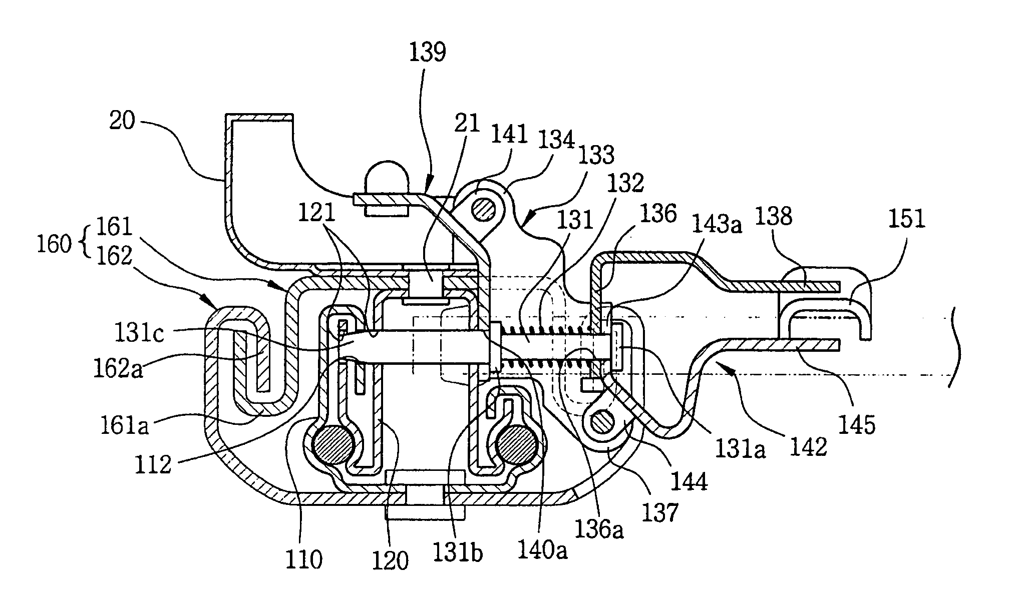
[0011] The present invention provides a seat slide mechanism for vehicles, in which the shape of a locker provided in a locking assembly is modified into an improved cylindrical structure with a circular cross section. The locker exhibits a higher mechanical rigidity as compared to a conventional plate type locker and effectively prevents a half-locked condition frequently occurring in the plate type locker. A reinforced channel structure of a combined hook configuration enables an upper reinforced channel and a lower reinforced channel to perform a mutual locking against upward loads. The reinforced channel structure is installed at the rear end portion of a rail assembly so as to effectively prevent damage of the rail assembly upon the exertion of a load of a three-point-type seat belt for the middle or second seat.

Problems solved by technology

However, the conventional seat slide mechanism, intended to provide convenience to a passenger occupant seated on the second and third row, is structured such that it does not endure a mechanical strength of 3.2 ton / 1 person required at the time of applying a three-point type seat belt for the middle seat.
That is, for such a conventional seat slide mechanism, there occurs a problem in that since it is structured to be applied to a one-person seat, if it is applied to a two-person bench seat, the seat slide structure is easily damaged (i.e., separated or widened) due to insufficient mechanical strength.
Particularly, in the case where the three-point type seat belt for the middle seat is applied to the two-person bench seat, the slide mechanism is apt to be easily damaged as a result of its insufficient mechanical rigidity.
This does not sufficiently meet the mechanical strength required at the time of applying a three-point type seat belt for the middle seat.
This contributes to serious deterioration of stability.

Method used


Image

  • Seat slide mechanism for vehicles
  • Seat slide mechanism for vehicles
  • Seat slide mechanism for vehicles

Examples


Embodiment Construction

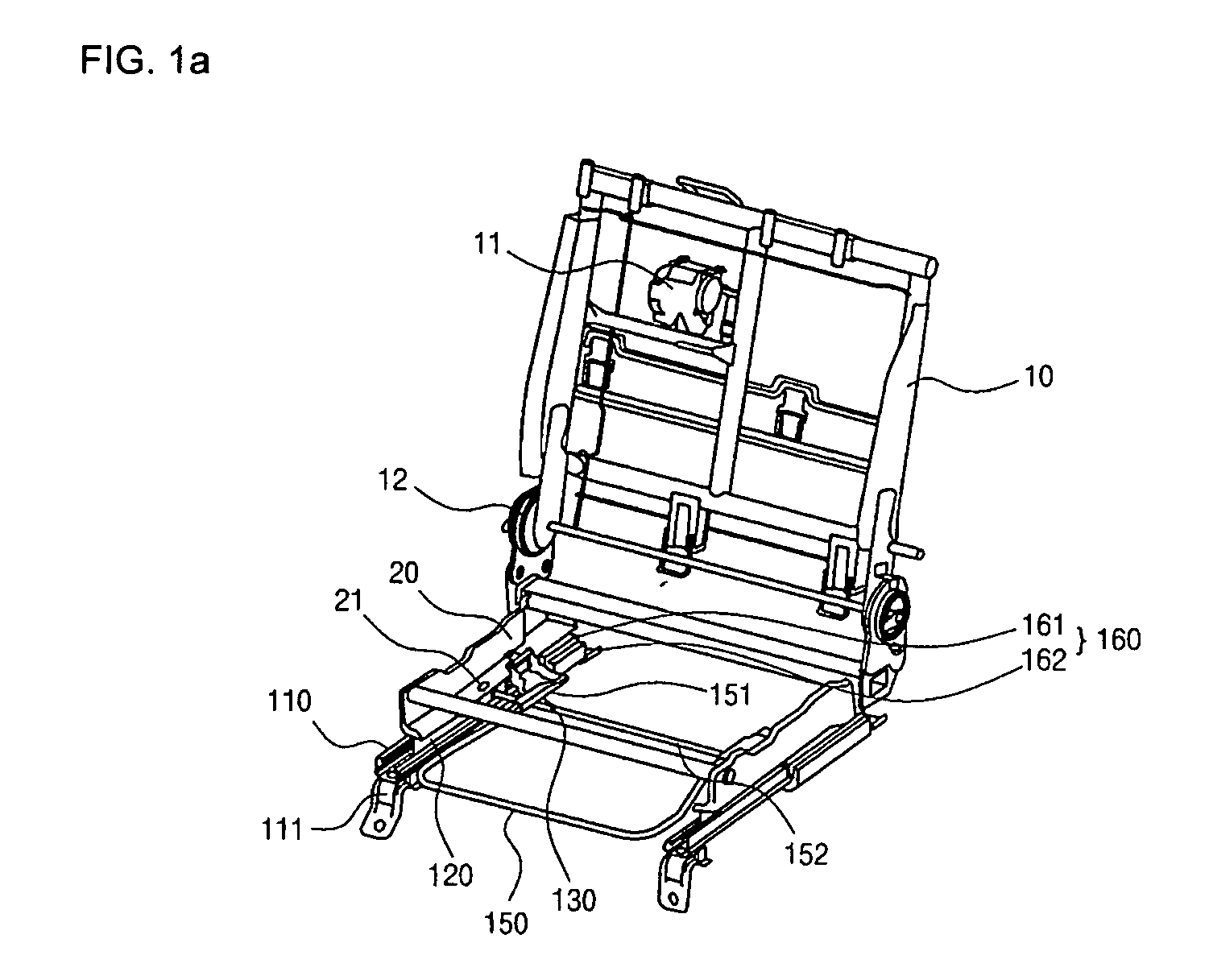
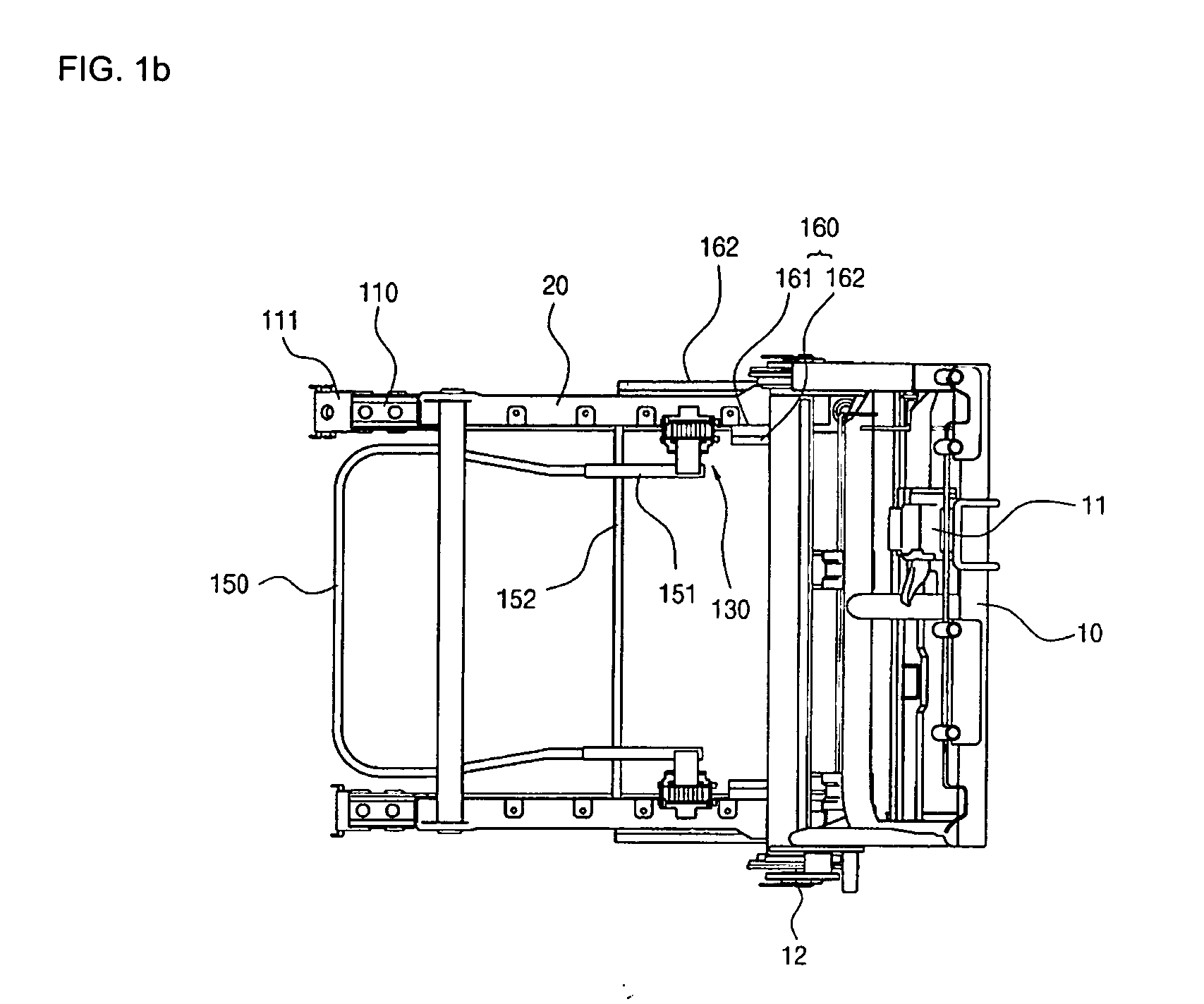
[0027] According to FIGS. 1a and 1b, a retractor 11 included in a three-point type seat belt for the middle seat is mounted on a seat frame 10. A lower cushion frame 20 is connected to the seat frame 10 by means of a recliner 12 and is integrally coupled with an upper rail 120 so that it can move forwards and backward on a lower rail 110 fixed to a vehicle body. The seat slide mechanism according to the present invention includes a lower rail 110 that is securely fixed to a vehicle body. An upper rail 120 is rested on the lower rail 110 and is movable forwards and backwards, with respect to the lower rail 110, together with a seat cushion frame 20. A locking assembly 130 serves to selectively perform a locking and an unlocking between the lower rail 110 and the upper rail 120, and an operating lever 150 enables a locking and unlocking of the locking assembly 130.

[0028] The lower rail 110 is securely fixed at both front and rear ends to the vehicle body by means of a mounting bracke...


PUM


Abstract

The shape of a locker provided in a locking assembly for a seat slide mechanism is modified into a cylindrical structure with a circular cross section so as to exhibit a higher mechanical rigidity as compared to a conventional plate type locker. Thereby, effectively preventing a half-locked condition. A reinforced channel structure, of a combined hook configuration, enables an upper reinforced channel and a lower reinforced channel to perform mutual locking against upward loads, thus effectively preventing damage of the rail assembly upon the exertion of a load of a three-point-type seat belt for the middle or second seat.

Description

CROSS REFERENCE TO RELATED APPLICATION(S) [0001] This application is based on, and claims priority to, Korean Patent Application No. 2004-78503, filed on Oct. 2, 2004, the disclosure of which is hereby incorporated by reference. TECHNICAL FIELD OF THE INVENTION [0002] The present invention generally relates to a seat slide mechanism for vehicles. More particularly, the seat slide mechanism includes a locker provided in a locking assembly and having a shape modified into a cylindrical structure with a circular cross section. BACKGROUND OF RELATED ART [0003] Typically, a seat for vehicles includes a slide mechanism that can move forwards and backwards to conform to the body shape of an occupant of the vehicle and a recliner that can adjust a tilt angle of a seat back. The slide mechanism typically refers to a device that enables forward and backward adjustment of the position of the vehicle seat. Such a typical seat slide mechanism basically includes a lower rail that is securely fixe...

Claims


Application Information

Patent Timeline
IPC IPC(8): F16M13/00
CPCB60N2/0705B60N2/0806B60N2/0825B60N2/0868B60N2/08
Inventor KIM, SANG HO
Owner KIA MOTORS CORP
Learn More