
Threaded connection for drill pipes

a drill pipe and thread connection technology, applied in the direction of hose connection, screw threaded joint, mechanical equipment, etc., can solve the problems of significant design challenge, achieve high compressive, tensile and bending stress, reduce bending stress, and low profile

Inactive Publication Date: 2006-04-06
ARGUS MACHINE
View PDF46 Cites 13 Cited by
  • Summary
  • Abstract
  • Description
  • Claims
  • Application Information

AI Technical Summary

Benefits of technology

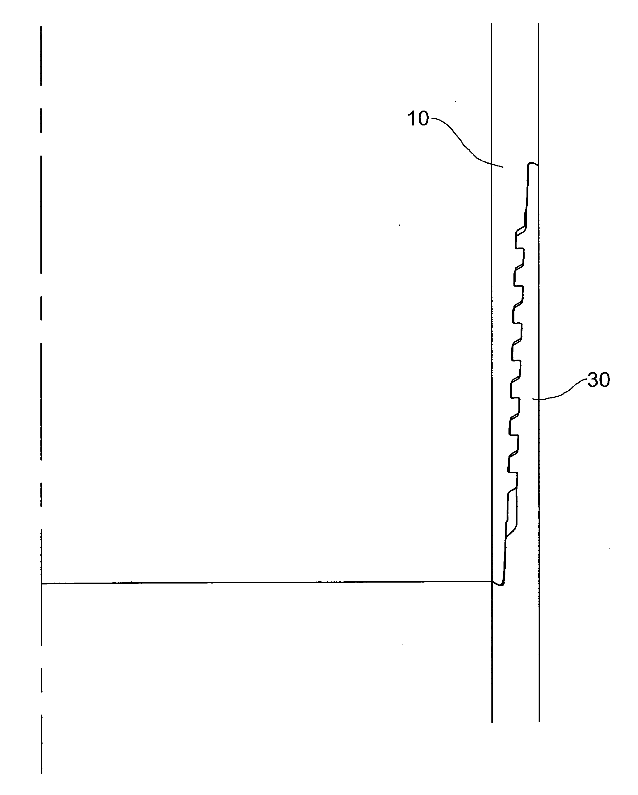
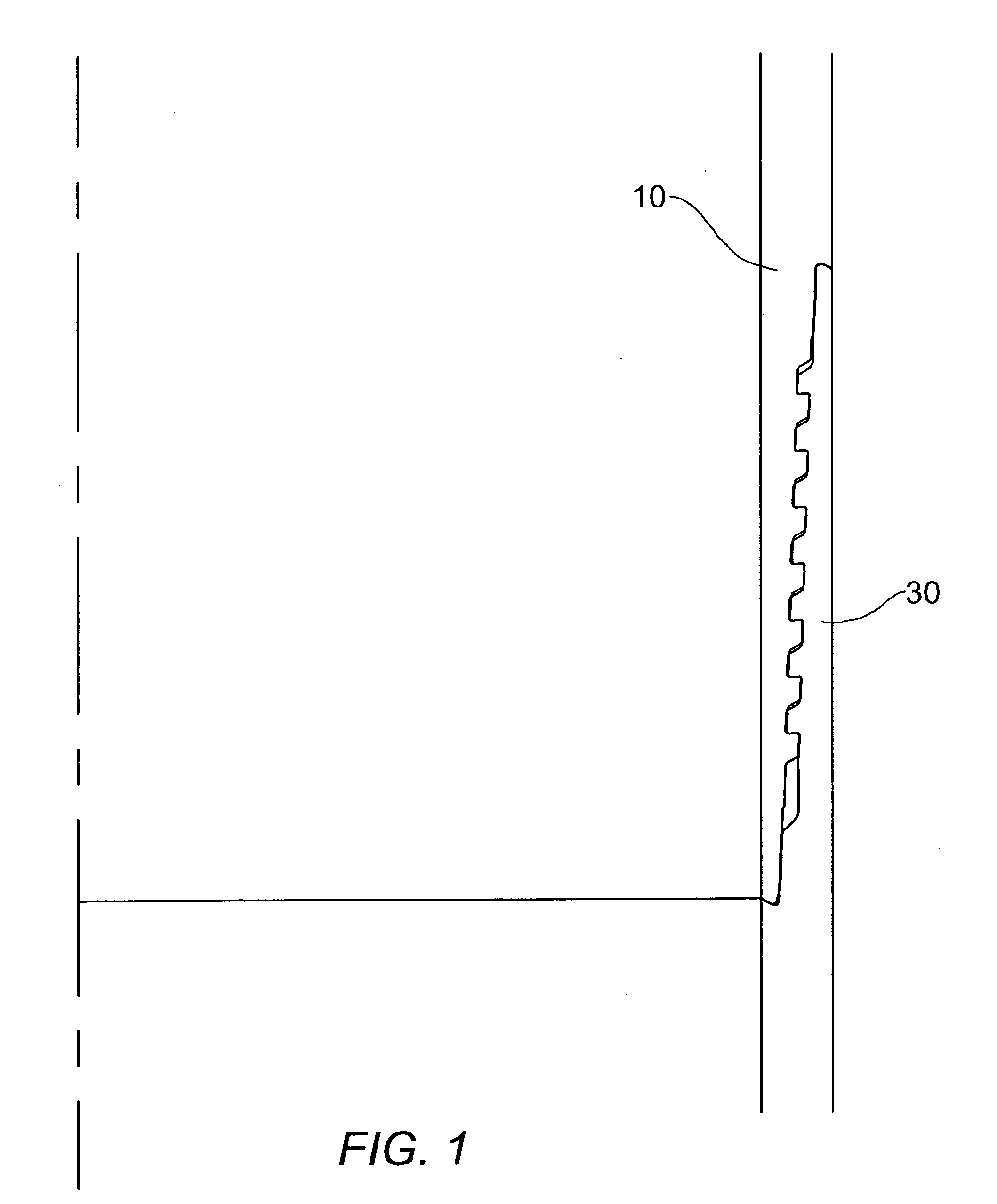
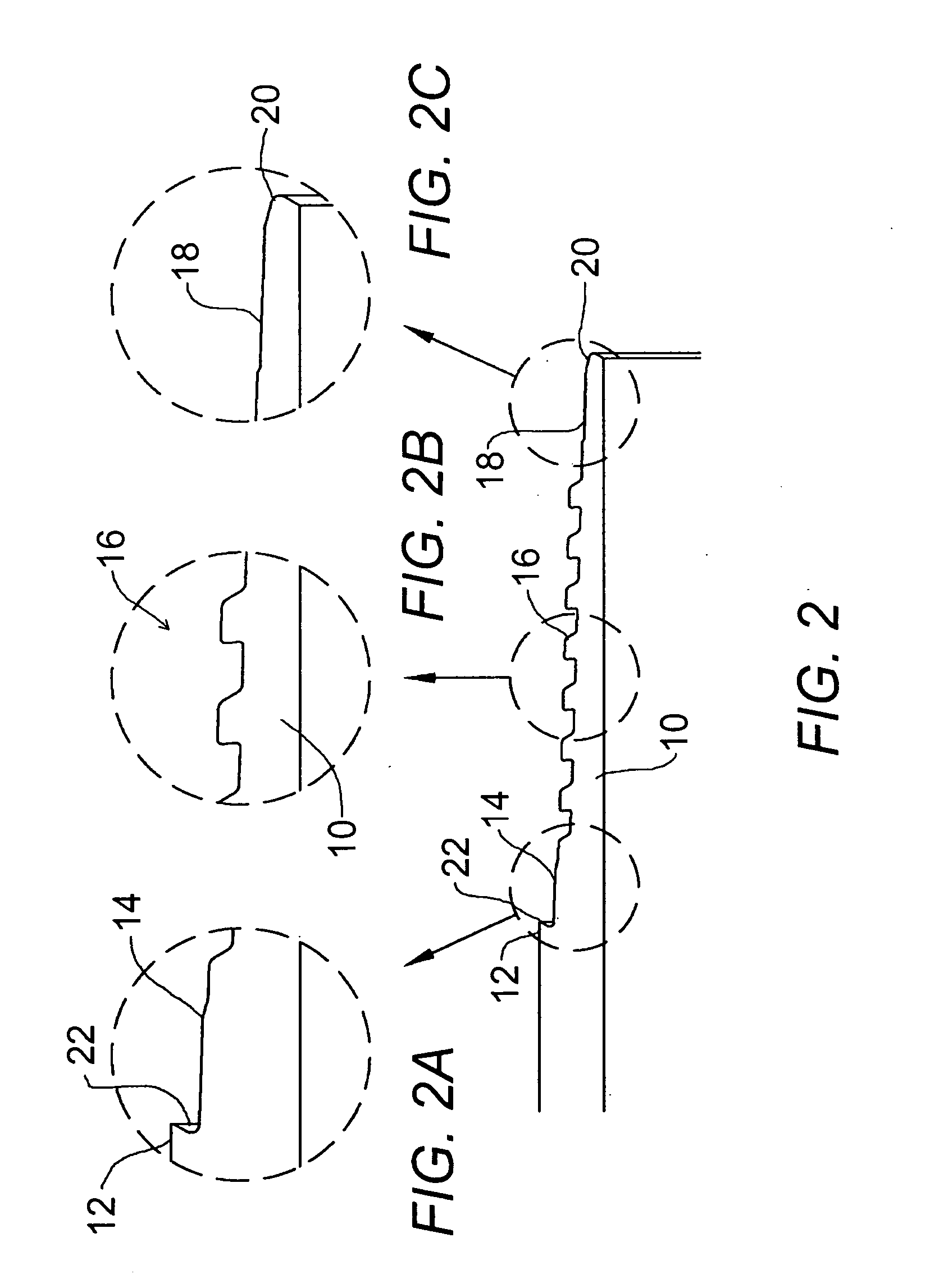
[0004] An improved threaded connection for use in drill pipe, as for example used in directional drilling along curved paths, is therefore provided that can withstand high compressive, tensile and bending stresses. A pin and box of a threaded connection are provided with interference fit metal-to-metal seals on both sides of a reverse thread section. In further aspects of the invention, the pin nose and box nose respectively are received in undercuts in the box shoulder and nose shoulder. In a further aspect of the invention, the pin nose and box nose engage the respective shoulders at the same time on make-up. Preferably, the thread section has a low profile, and the pin and box are kept short to reduce bending stresses.

Problems solved by technology

Providing a threaded connection in such drill pipe that can withstand high compressive, tensile and bending stresses poses a significant design challenge.

Method used


Image

  • Threaded connection for drill pipes
  • Threaded connection for drill pipes
  • Threaded connection for drill pipes

Examples


Embodiment Construction

[0018] While the invention is susceptible of various modifications and alternative constructions, certain illustrated embodiments thereof have been shown in the drawings and will be described below in detail. It should be understood, however, that there is no intention to limit the invention to the specific form disclosed, but, on the contrary, the invention is to cover all modifications, alternative constructions, and equivalents falling within the spirit and scope of the invention as defined in the claims.

[0019] In this patent application, the use of the word comprising does not exclude other elements being present. In addition, a reference to an element by the indefinite article “a” does not exclude the possibility that more than one of the elements is present.

[0020] The threaded connection of the present invention is designed for use on a drill pipe that is to be used for drilling along an arcuate path in a drill string made up of connected lengths of cooperating drill pipes. ...


PUM


Abstract

A pin and box of a threaded connection are provided with interference fit metal-to-metal seals on both sides of a reverse thread section. The pin nose and box nose respectively are received in undercuts in the box shoulder and nose shoulder. The pin nose and box nose engage the respective shoulders at the same time on make-up. The thread section has a low profile, and the pin and box are kept short to reduce bending stresses.

Description

PRIORITY [0001] This application claims the priority date of the Canadian application entitled Threaded Connection for Drill Pipes filed by Thomas A. M. Hallett on Sep. 28, 2004 with application number 2,481,609. DESCRIPTION BACKGROUND OF THE INVENTION [0002] Background Information. Horizontal and directional drilling allows drill rig operators to follow multiple pre-planned drilling paths from a single well-head. Advances in drill tools permit accurate location of the drill bit and steering of the drill bit along the pre-planned drilling path. Drilling multiple drill holes from a single well-head necessitates that the drill string follow an arcuate path. Drill pipe used in directional drilling may be thin-walled 5¼ OD pipe with a ¼ inch wall thickness. At the threaded connections between adjacent drill pipes in the drill string, the walls of the pins and boxes narrow to less than ⅛ inch. Providing a threaded connection in such drill pipe that can withstand high compressive, tensile...

Claims


Application Information

Patent Timeline
IPC IPC(8): F16L25/00
CPCE21B17/042F16L15/004
Inventor HALLETT, THOMAS A.M.WILTERMUTH, RANDY
Owner ARGUS MACHINE
Learn More