Method and apparatus for controlling a variable speed fan in an image forming device

a variable speed fan and control method technology, applied in the direction of motor/generator/converter stopper, dynamo-electric converter control, instruments, etc., can solve the problems of large noise level and general low frequency of the “tach” signal in these low-cost fans, and provide enough information for a host devi

Active Publication Date: 2006-04-06
LEXMARK INT INC
View PDF1 Cites 7 Cited by
  • Summary
  • Abstract
  • Description
  • Claims
  • Application Information

AI Technical Summary

Benefits of technology

[0008] Accordingly, it is an advantage of the present invention to provide a fan control circuit and operating method that provides suitable control of inexpensive fans that exhibit a low-frequency tachometer output signal.
[0009] It is another advantage of the present invention to provide a fan control circuit that provides an initial output signal to drive an inexpensive fan to an initial rotational speed, and then by using a low-frequency tachometer feedback signal provided by the fan, automatically adjusts the actual fan speed if needed, so that the final fan speed is within a predetermined range.
[0010] It is a further advantage of the present invention to provide a fan control circuit that provides a DC control signal for an inexpensive fan, and then receives a tachometer feedback signal and conditions that feedback signal into a logic signal that is suitable for use with low-voltage level logic, including microcomputers and microprocessors.
[0011] It is yet another advantage of the present invention to provide a fan control circuit and operating method that determines an actual fan rotating speed and compares that to a desired fan rotating speed, then automatically makes adjustments to the fan speed if necessary, and further stores additional operating parameters into a non-volatile memory for future use by the fan control circuit.
[0012] It is still another advantage of the present invention to provide a fan control circuit and operating method that initially controls an inexpensive fan to an initial rotating speed, then determines if that fan is running within a suitable range of rotational speeds, and if not, determines if a fine adjustment should be made to the fan's rotational speed, and if not, determines whether a coarse adjustment should be made to the fan's rotational speed, and then makes the appropriate adjustments until the actual fan rotational speed is within acceptable operating tolerances.
[0013] Additional advantages and other novel features of the invention will be set forth in part in the description that follows and in part will become apparent to those skilled in the art upon examination of the following or may be learned with the practice of the invention.

Problems solved by technology

The designer can always install a fan that blows more air, but this approach quite often causes a greater noise level that usually is undesirable.
The frequency of the “tach” signal in these low cost fans is generally too low to provide enough information for a host device to use conventional motor control means for actively controlling the speed of the fan.

Method used


Image

  • Method and apparatus for controlling a variable speed fan in an image forming device
  • Method and apparatus for controlling a variable speed fan in an image forming device
  • Method and apparatus for controlling a variable speed fan in an image forming device

Examples


Embodiment Construction

[0023] Reference will now be made in detail to the present preferred embodiment of the invention, an example of which is illustrated in the accompanying drawings, wherein like numerals indicate the same elements throughout the views.

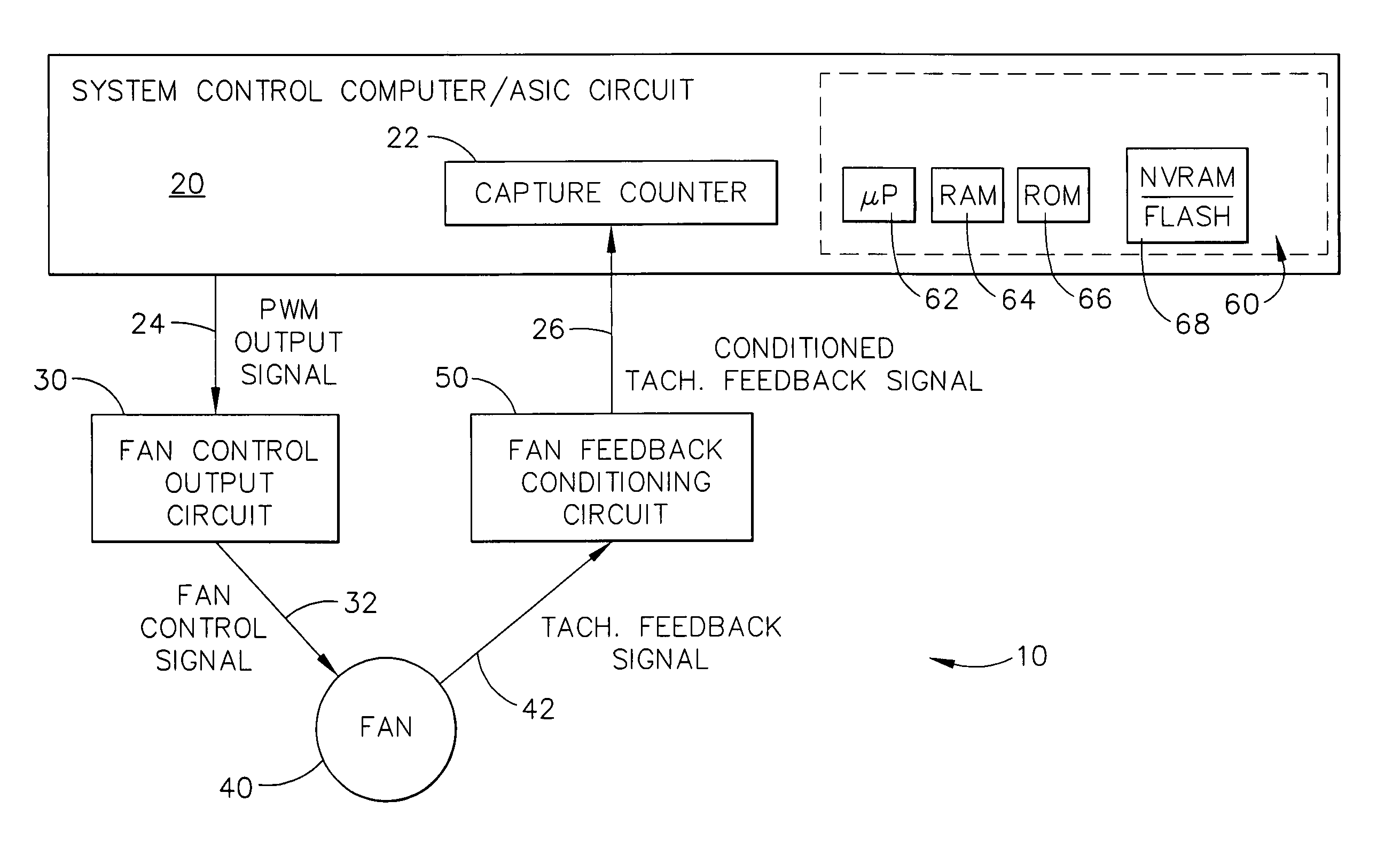
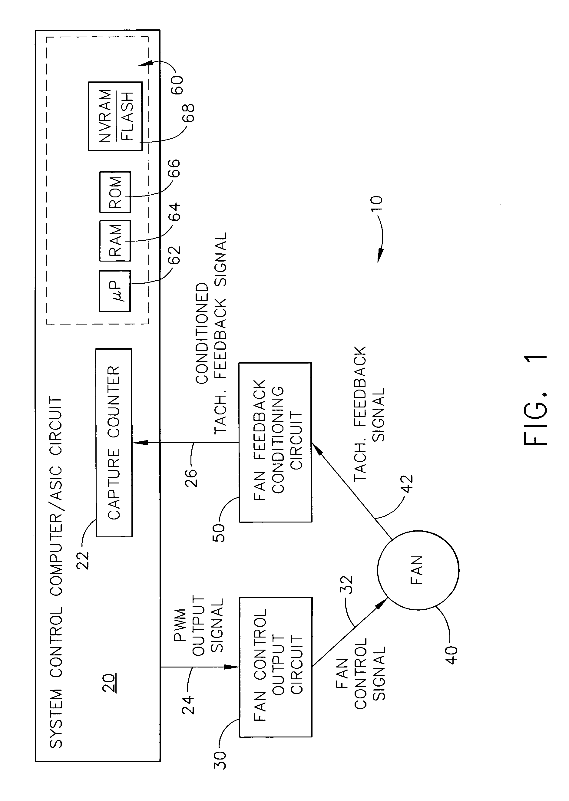
[0024] As noted above, conventional control circuits and fan designs used in relatively inexpensive electrophotographic or “EP” printers (e.g., laser printers) may allow the possibility of a relatively wide variation in fan speed for a given output control signal from the controller, due to variation in manufacturing tolerances and other parameters. In addition, the fan's response to a received control input signal may be non-linear, due to either the fan's design or to its interaction with the host device's control circuitry. A given fan typically is assumed to operate consistently with itself over time within an assumed tolerance (although there can be some thermal drift), but it is desirable that fan-to-fan variation be minimized in the system. The p...


PUM


Abstract

An improved variable speed fan controller for use in devices such as laser printers. The controller automatically adjusts its output signal to fans such that a fan quickly settles into an appropriate operating speed, even if the fan has been newly installed into the equipment. The controller can store values in non-volatile memory, if desired, to keep track of recent changes in the fan's operating parameters and corresponding control signal values. The controller is able to control relatively inexpensive fans that don't necessarily operate at a predictable fan rotating speed under repeatable conditions and control signals, by controlling the fan to an initial or predetermined rotating speed; if the fan isn't running within a suitable range of rotational speeds, then determining whether a fine or coarse adjustment should be made to the fan's rotational speed. The controller makes appropriate adjustments until the fan's rotational speed is within acceptable operating tolerances.

Description

TECHNICAL FIELD [0001] The present invention relates generally to image forming equipment and is particularly directed to equipment of the type which includes a fan for cooling. The invention is specifically disclosed as a variable speed fan and controller that quickly settles into an appropriate operating speed, even if the fan has been newly installed into the equipment. BACKGROUND OF THE INVENTION [0002] In many modern electronic devices a cooling fan is used to regulate the temperature of the device during operation. In most laser printers, this is an especially important design element due to the presence of an active heating element, typically a fuser that melts the toner to the paper. In such equipment, the cooling fan must be controlled in such a way so as to strike a suitable balance between two competing goals of controlling the internal temperature of the device and minimizing the acoustic impact of the device upon its environment. The designer can always install a fan th...

Claims


Application Information

Patent Timeline
Patent Type & Authority Applications(United States)
IPC IPC(8): H02P5/06H02P7/00
CPCG06F1/206G03G21/206
Inventor ABLE, DOUGLAS ANTHONYALVERSON, DAVID HERMANCHAPMAN, DANNY KEITHCUTTS, DAVID ROSS JR.JACOBS, BRIAN MICHAELMILES, MATTHEW DAVIDPHILLIPS, MICHAEL TODDSHEPHERD, BENJAMIN KYLEUNDERWOOD, MARK STEPHENWHITE, MARSHALL LEE
Owner LEXMARK INT INC
Why Eureka
Try Eureka