Snubber circuit

Inactive Publication Date: 2006-04-06
DICKINSON ROGER B CEO TORRINGTON RES CO +1
View PDF3 Cites 26 Cited by
  • Summary
  • Abstract
  • Description
  • Claims
  • Application Information

AI Technical Summary

Benefits of technology

[0005] In a somewhat more sophisticated design, a first resistor and a first unidirectional element, preferably a diode, in series with each other and with the capacitor are provided in parallel arrangement with a second resistor and second unidirectional element also in series with each other and the capacitor. The diodes are arranged to provide for current flow in one and an opposite direction to and from the capacitor and the first and second resistors respectively provide a first level of resistance for damping during ringing and a second and different level of resistance during current flow in the opposite direction during turn on.

Problems solved by technology

Using such a snubber with integrated power supply control circuits may pose a problem, in that the control circuit may shut down while trying to absorb the energy stored in the capacitor.
Reducing the size of the snubber capacitor of course solves this problem but may well result in a capacitor incapable of controlling the ringing.

Method used


Image

  • Snubber circuit
  • Snubber circuit
  • Snubber circuit

Examples


Embodiment Construction

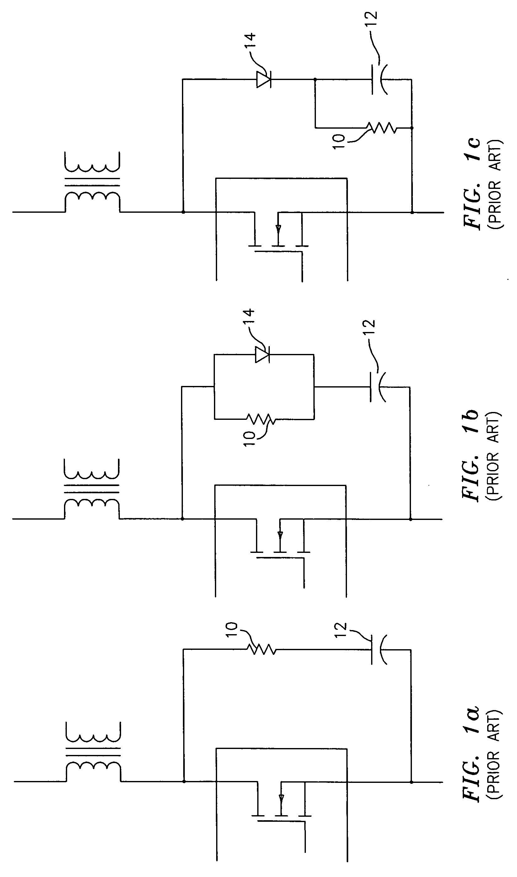
[0012]FIG. 1a shows the simplest form of a snubber circuit. Resistor 10 affects charging and discharging of capacitor 12 equally. This limits the amount of energy that can be stored to the amount which can be discharged during the shortest period of the operating cycle.

[0013] In FIG. 1b illustrates that this limitation can be overcome by adding a diode 14 through which the capacitor charges. Thus, the capacitor can have a smaller value than in FIG. 1a. However the resistor still needs to be sized to discharge this energy during the off time of the switch.

[0014] The circuit of FIG. 1c acts to limit the resonant voltage swings to a determined value, which will change depending on duty cycle.

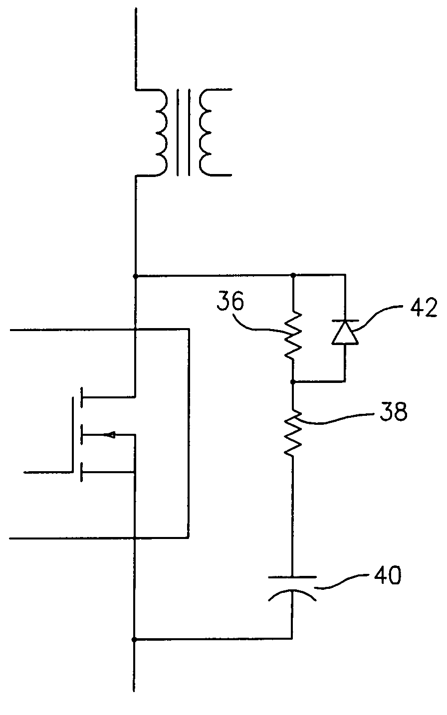
[0015] Using a snubber circuit of the type described with Integrated power supply control circuits poses a problem, in that the control circuit will shut down trying to absorb the energy stored in the snubber capacitor. Reducing the size of the capacitor solves the turn off problem but results i...


PUM


Abstract

A snubber circuit for use with an integrated power supply control circuit incorporating a transformer and a lateral power MOSFET on a single silicon chip. A capacitor is provided in circuit with the MOSFET and first resistor and diode are in series with each other and the capacitor. A second resistor and diode are also in series with each other and the capacitor. The diodes provide for first current flow in one and an opposite direction and the resistors provide first and second levels of resistance respectively for damping and turn on.

Description

BACKGROUND OF INVENTION [0001] Snubber circuits have many applications in power electronics circuits such as voltage and or current rise limiters, level clamps, EMI limiters, and damping networks. Prior art snubber circuits, to be discussed hereinbelow, control the snubbing action under one set of circuit conditions, i.e. during switch on or switch off time. Snubbing is accomplished by selectively storing energy in a capacitor during one portion of an operating cycle and discharging the energy during a second portion of the cycle. [0002] Using such a snubber with integrated power supply control circuits may pose a problem, in that the control circuit may shut down while trying to absorb the energy stored in the capacitor. Reducing the size of the snubber capacitor of course solves this problem but may well result in a capacitor incapable of controlling the ringing. [0003] A general object of the present invention is to provide a snubber circuit which can provide two levels of curren...

Claims


Application Information

Patent Timeline
IPC IPC(8): H02H9/00
CPCH02M1/34H02M3/335H02M2001/348H03K17/08142H03K17/162H02M1/348
Inventor YUNUS, HAROON I.
Owner DICKINSON ROGER B CEO TORRINGTON RES CO
Why Eureka
Try Eureka