Method and apparatus for configuring an automatic cross connect system at a remote wiring hub

a technology of automatic cross-connecting and wiring hub, which is applied in the field of providing connectivity for telephony services at a remote hub, can solve the problems of high costs associated with providing connectivity at the hub, and achieve the effects of reducing the cross-connect point and the size of the switch, reducing the dispatch cost associated with providing service connectivity at the hub, and reducing space constraints

Inactive Publication Date: 2006-04-06
ALCATEL-LUCENT USA INC
View PDF5 Cites 0 Cited by
  • Summary
  • Abstract
  • Description
  • Claims
  • Application Information

AI Technical Summary

Benefits of technology

[0013] In one embodiment, the present invention is implemented as a hub configuration software tool illustratively located at a central office. The hub configuration software tool may be used by service providers to configure the cross-connect points between the subscriber lines and feeder lines on a hub-by-hub basis. The present invention is applicable for hubs providing POTS service, DSL service (with or without line-sharing), and an integrated POTS / DSL solution. Accordingly, the present invention helps alleviate space constraints at the hubs by reducing the cross-connect points and sizes of the switches. Further, dispatch costs associated with providing service connectivity at the hub are reduced by connecting the subscriber lines to the feeder lines based on penetration and churn rates of the subscriber lines.

Problems solved by technology

Accordingly, we have recognized that there is a need for a method an apparatus that assists in optimizing connectivity between subscriber lines and feeder lines at a remote hub, since the hubs have limited space and high costs associated with providing connectivity at the hubs may be considerable.

Method used


Image

  • Method and apparatus for configuring an automatic cross connect system at a remote wiring hub
  • Method and apparatus for configuring an automatic cross connect system at a remote wiring hub
  • Method and apparatus for configuring an automatic cross connect system at a remote wiring hub

Examples


Embodiment Construction

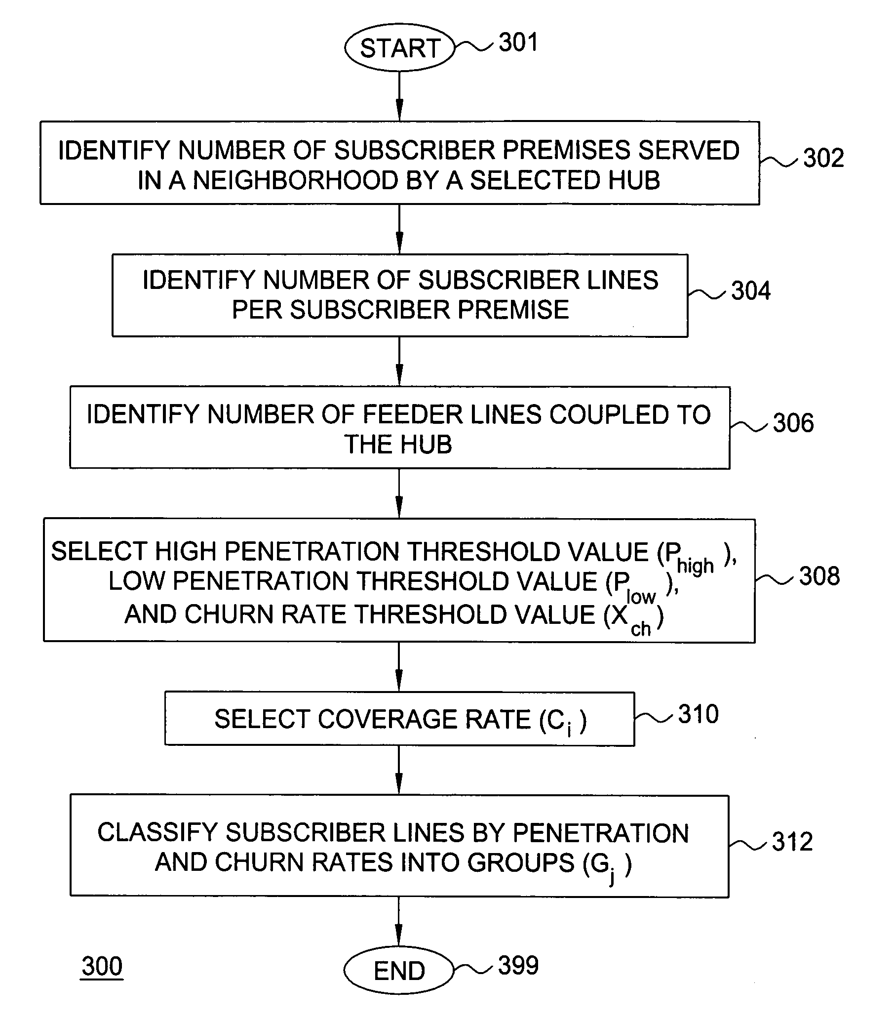
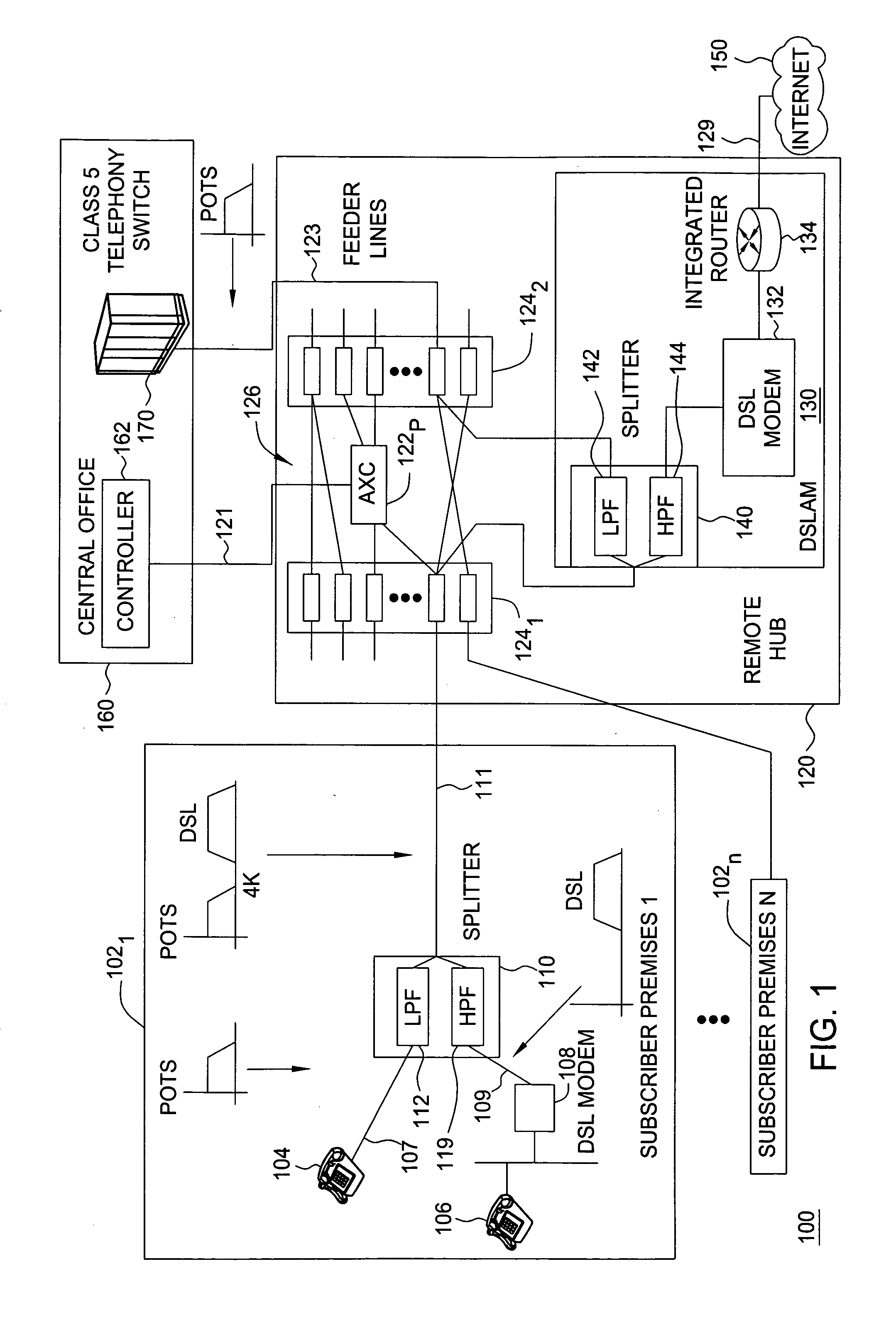
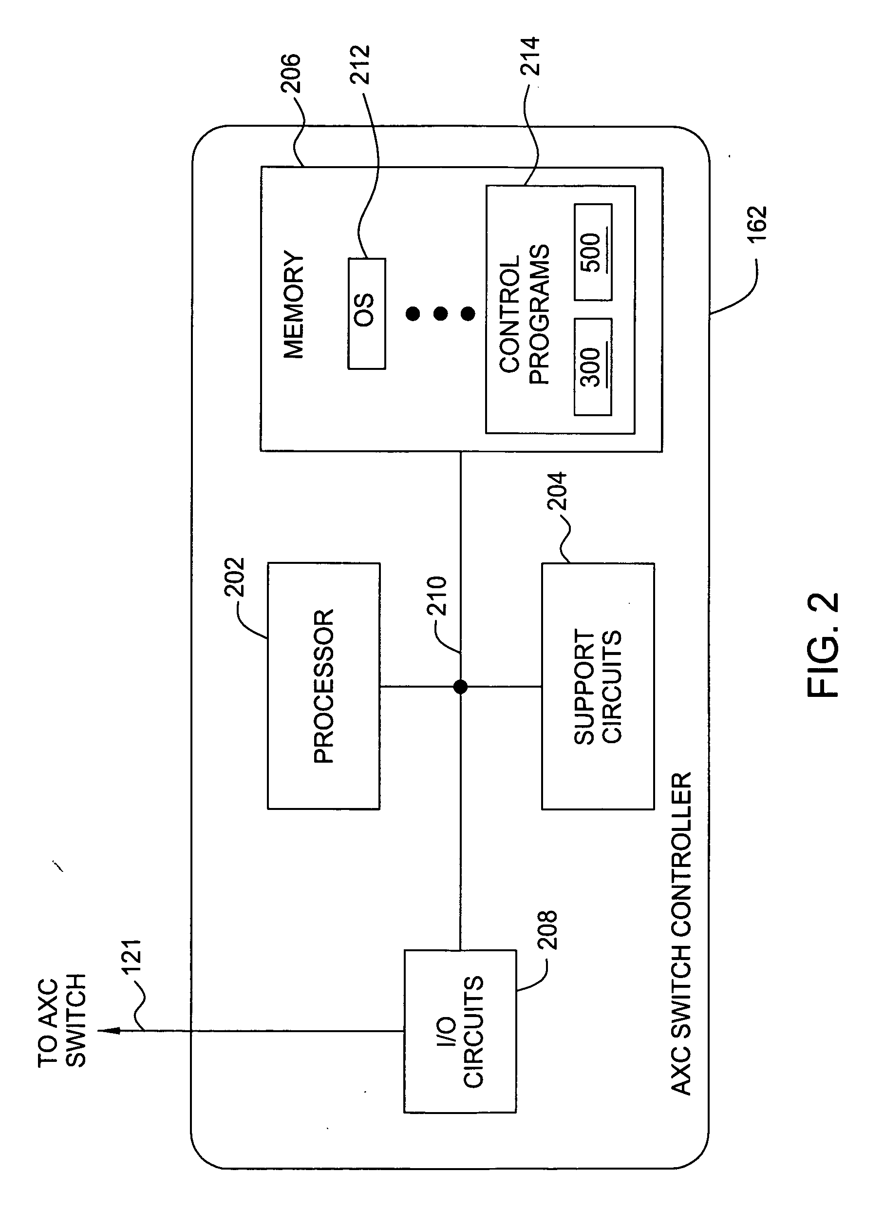
[0028] The present invention provides a method and apparatus to configure connectivity at a remote hub, based on application and service specific characteristics. In one embodiment, the present invention may be implemented as a software tool that is installed on a processor system at a central office of a service provider. The present invention is capable of characterizing subscriber lines by their penetration rates and turnover (churn) rates to the subscriber premises and then group the subscriber lines accordingly. The present invention then determines how the subscriber lines of each group should be optimally connected to the feeder lines, which route to the central office. Specifically, the subscriber lines of a selected group may be routed directly to the feeder lines, coupled to the feeder lines via an automatic cross-connect (AXC) switch, or terminated at the hub, based on predetermined policies associated with the penetration rates and churn rates of the subscriber lines.

[0...


PUM


Abstract

A method and apparatus for configuring connectivity at a hub having a plurality of subscriber lines from a plurality of subscriber premises and a plurality of feeder lines from a central office. The hub provides connectivity between the plurality of subscriber premises and the central office. The method and apparatus include categorizing the plurality of subscriber lines into a plurality of groups based on penetration rates and churn rates of the plurality subscriber lines. Each group of subscriber lines are connected to feeder lines based on the penetration and churn rates for POTS and / or DSL services. Subscriber line groups with high penetration rates and high / low churn rates are coupled directly to feeder lines. Subscriber line groups with low penetration rates and high / low churn rates are terminated at the hub. Subscriber lines with an intermediate penetration rate are candidates for being connected to the feeder lines via an automatic switch.

Description

FIELD OF INVENTION [0001] The present invention relates to providing connectivity for telephony services at a remote hub. More specifically, the invention relates to optimizing size and configuration of cross connections between subscriber lines and feeder lines at a remote hub based on subscriber line usage and turnover characteristics. BACKGROUND OF INVENTION [0002] Telephony service providers of telephony (e.g., POTS and DSL) services utilize outside plants that provide connectivity from the subscribers of the service to the central offices (CO) of the service provider. The most common media used in the outside plant is copper loops. A copper loop typically transverses from the CO to the subscriber homes via manholes, wiring cabinets, pedestals, and poles before terminating at the network interface device (NID) at the subscribers' premises. [0003] The manholes and cabinets represent major concentration sites for the wiring. Each cabinet or manhole (i.e., remote hub) typically ser...

Claims


Application Information

Patent Timeline
Patent Type & Authority Applications(United States)
IPC IPC(8): H04J1/16
CPCH04M11/062H04Q3/605H04Q2213/1302H04Q2213/13039H04Q2213/1304H04Q2213/13076H04Q2213/13109H04Q2213/13298
Inventor CHU, THOMAS P.GAGEN, PAUL FRANCISMAGEE, FRANCIS ROBERT
Owner ALCATEL-LUCENT USA INC
Why Eureka
Try Eureka