Object recognition apparatus

a technology of object recognition and object, which is applied in the direction of distance measurement, pedestrian/occupant safety arrangement, instruments, etc., can solve the problems of increasing the cost of the apparatus, difficult in general for the stereo camera to detect objects, and difficult to accurately find the distance up to the target object, etc., to reduce the installation space, high reliability, and low cost

Inactive Publication Date: 2006-04-06
OLYMPUS CORP
View PDF5 Cites 78 Cited by
  • Summary
  • Abstract
  • Description
  • Claims
  • Application Information

AI Technical Summary

Benefits of technology

[0015] Accordingly, an object of the present invention is to provide an object recognition apparatus which can recognize an object with extremely high reliability by both a stereo camera and an active range finder, and which can reduce an installation space, and can be manufactured at a low cost.

Problems solved by technology

It is difficult in general for the stereo camera to detect an object and detect a distance appropriately in a dark place.
Further, when a target object is in a low contrast even in a bright place, it is difficult to accurately find a distance up to the target object.
In a video camera using infrared radiation or a laser beam as a fill light, it is necessary to add a light source for emitting a fill light, which results in an increase in cost for the apparatus.
Namely, according to the stereo camera, it is impossible to accurately detect a distance up to a target object which is a long way off.

Method used


Image

  • Object recognition apparatus
  • Object recognition apparatus
  • Object recognition apparatus

Examples


first embodiment

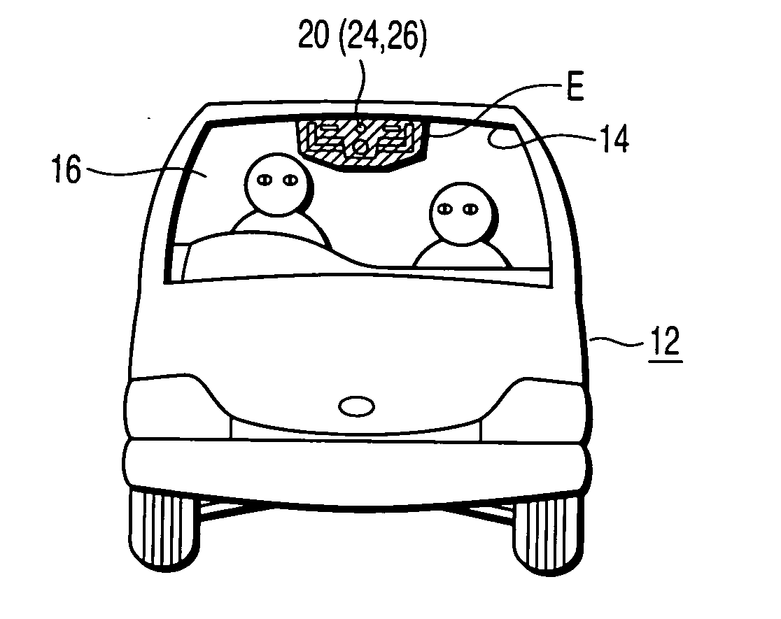
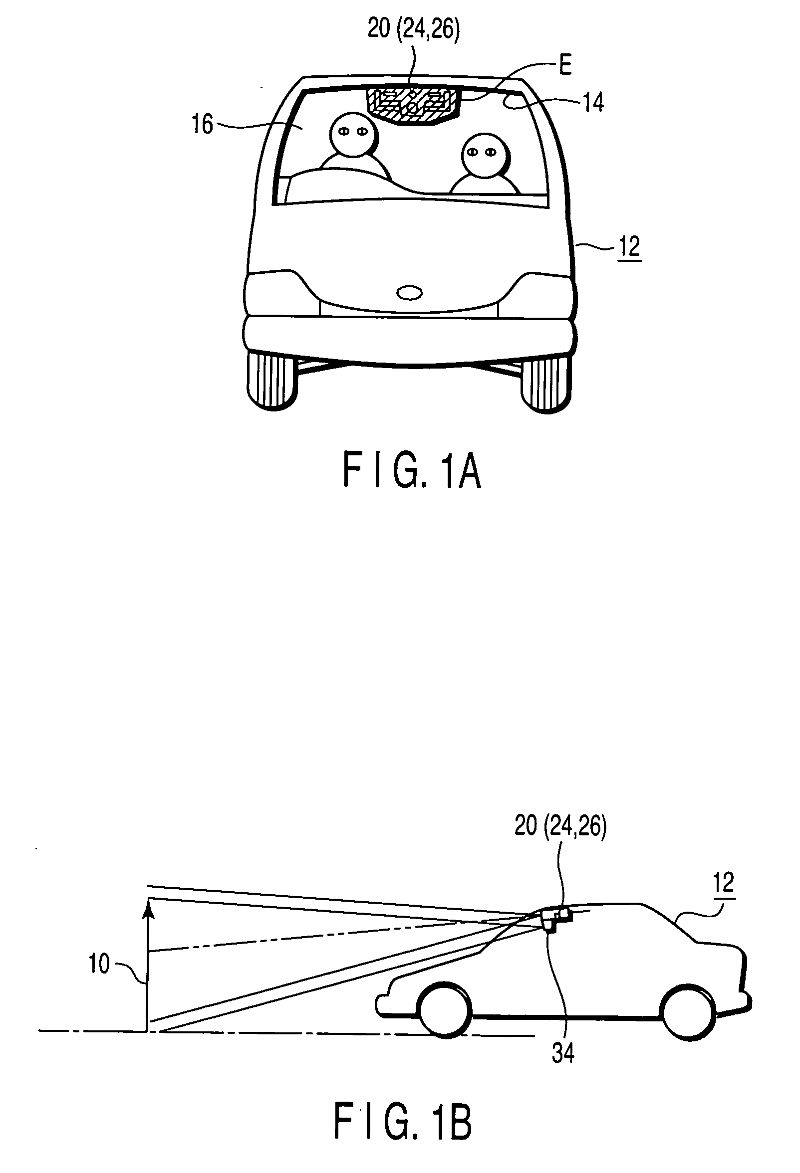
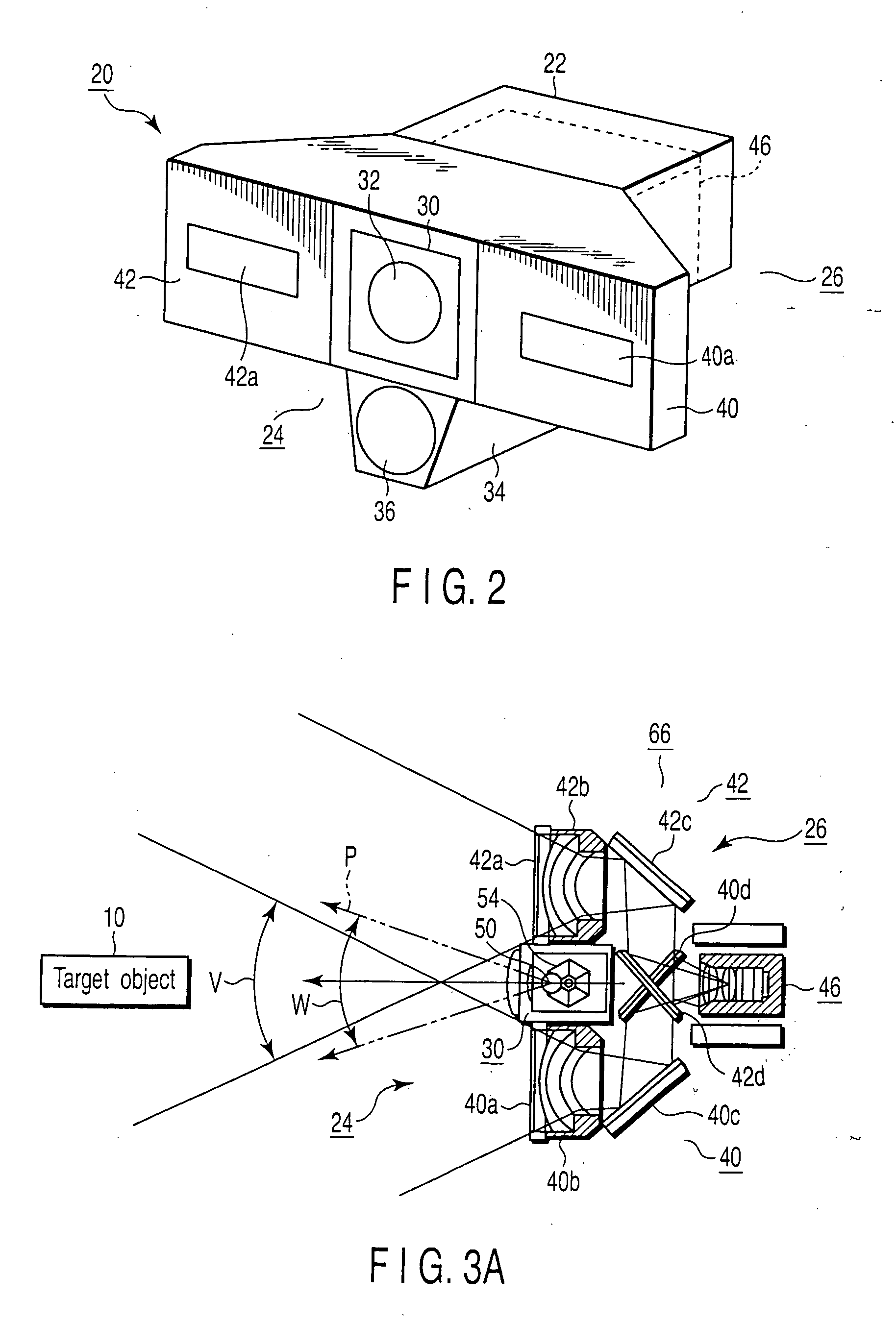
[0084]FIGS. 1A and 1B are views showing one example in which an object recognition apparatus according to a first embodiment of the present invention is applied to a vehicle (passenger car), where FIG. 1A is an exterior appearance front elevation viewed from the front of the vehicle, and FIG. 1B is a schematic explanatory diagram viewed from a side of the vehicle. FIG. 2 is a perspective view showing an exterior appearance of the object recognition apparatus according to the first embodiment of the invention.

[0085] As shown in FIGS. 1A, 1B and 2, an object recognition apparatus 20 is attached inside a vehicle interior 14 of a vehicle 12. The object recognition apparatus 20 is configured such that an active range finder 24 composed of, for example, a laser radar, and a stereo camera 26 are integrally housed in a case 22 serving as a housing, which makes the both be a single unit.

[0086] A floodlight window 32 in a flood light unit 30 of the active range finder 24 is disposed at an u...

second embodiment

[0170] Next, a second embodiment of the present invention will be described.

[0171]FIGS. 14A, 14B and 15 show configurations of an object recognition apparatus 20 according to the second embodiment of the invention, the figures being shown so as to correspond to FIGS. 1A, 1B and 2, respectively.

[0172] The configurations of the object recognition apparatus in the second embodiment and embodiments described hereinafter are the same as those in the first embodiment. Therefore, only different configurations and operations will be described, the other portions which are the same as those are denoted by same reference numerals, and illustrations and descriptions thereof will be omitted.

[0173] The second embodiment is different from the first embodiment in that only the floodlight unit 30 of the active range finder 24 is installed in the vehicle so as to be integrated with the stereo camera 26, and that the light receiving unit 34 of the active range finder 24 is installed in the vicinit...

third embodiment

[0174] Next, a third embodiment of the present invention will be described.

[0175]FIG. 16 shows an operation of an object recognition apparatus according to the third embodiment of the invention, and is a timing chart showing charge storage periods of the image pickup device 76, movements on the inclined reflection surfaces of the polygon mirror 54, and timings of the light emission pulse irradiations of the laser light source (LD). FIGS. 17A to 17C are views showing a relationship among stereo images obtained by photographing three times by the object recognition apparatus 20 according to the present embodiment, and active projection irradiating ranges WL and WR.

[0176] The third embodiment is an embodiment corresponding to a case where the working speed of the polygon mirror 54 is not high as that in the first embodiment described above, and hexahedral driving of the polygon mirror 54 cannot be achieved, but only tetrahedral driving thereof can be achieved during one cycle. In thi...


PUM


Abstract

The object recognition apparatus has an active range finder having a floodlight unit which floodlights a light onto a target object, and determines a distance up to a target object on the basis of a reflected light therefrom, a stereo camera to determine a distance up to the target object on the basis of image information from the target object, an object recognition unit which recognizes the target object on the basis of an output signal from the active range finder and an output signal from the stereo camera, and a fill light control unit which controls the floodlight unit to operate so as to irradiate a light floodlit by the floodlight unit as a fill light of the stereo camera.

Description

CROSS REFERENCE TO RELATED APPLICATIONS [0001] This is a Continuation application of PCT Application No. PCT / JP2004 / 011927, filed Aug. 19, 2004, which was published under PCT Article 21(2) in Japanese.[0002] This application is based upon and claims the benefit of priority from prior Japanese Patent Application No. 2003-304710, filed Aug. 28, 2003, the entire contents of which are incorporated herein by reference. BACKGROUND OF THE INVENTION [0003] 1. Field of the Invention [0004] The present invention relates to an object recognition apparatus which is used to be mounted on a movable body such as an automobile, an airplane, a ship and a robot, or a non-movable body such as an outdoor monitoring system. [0005] 2. Description of the Related Art [0006] As an apparatus mounted on an automobile or the like, for recognizing an object in front thereof, a stereo camera has been known. This stereo camera has a function of observing a target object from different visual directions, and of me...

Claims


Application Information

Patent Timeline
Patent Type & Authority Applications(United States)
IPC IPC(8): G03B13/00G03B15/03G01C3/06G01S17/86B60R1/00B60R21/00G01C3/18G01S7/48G01S17/08G01S17/931G08G1/16
CPCG01C3/18G01S7/4802G01S17/023G01S17/936G01S17/86G01S17/931
Inventor ARAI, KAZUHIKOIWAKI, HIDEKAZUMIYOSHI, TAKASHI
Owner OLYMPUS CORP
Why Eureka
Try Eureka