Image forming apparatus
- Summary
- Abstract
- Description
- Claims
- Application Information
AI Technical Summary
Benefits of technology
Problems solved by technology
Method used
Image
Examples
embodiment 1
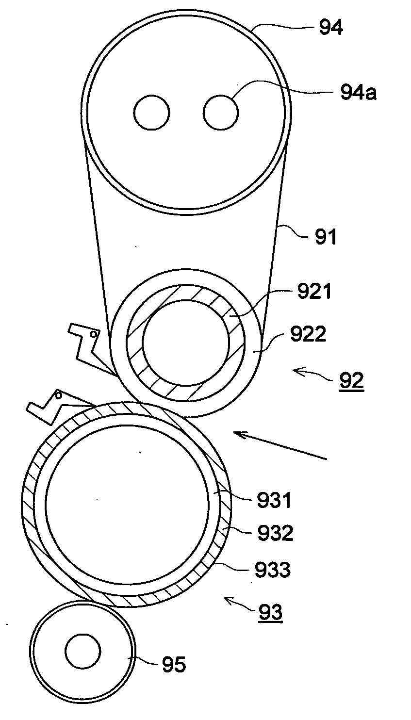
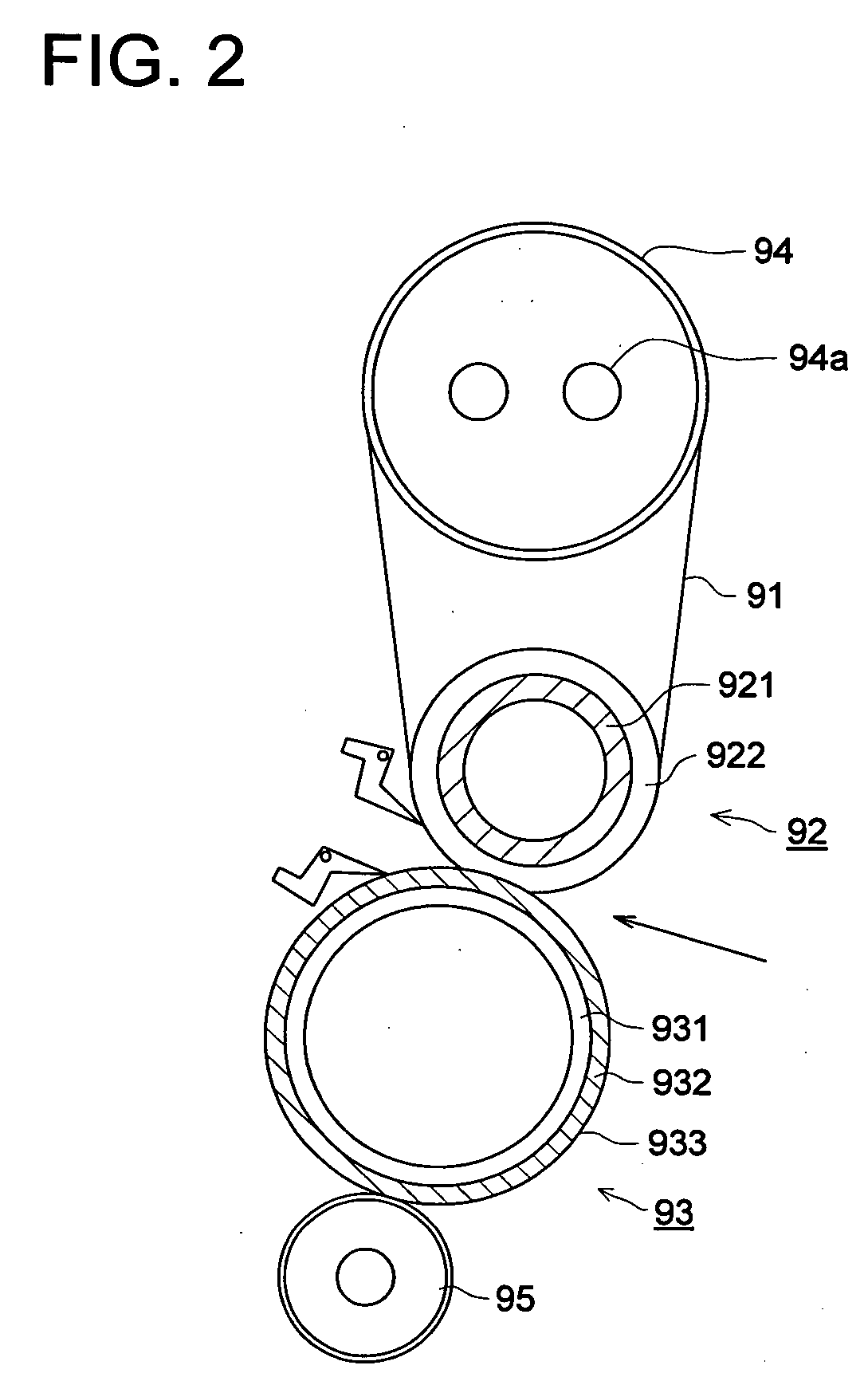
[0096] In the embodiment 1 shown in FIG. 5, although cross sectional shapes of a support pressing roller 92B and a external pressing roller 93B are the same as those of the support pressing roller 92A and the external pressing roller 93A, respectively, the width of the pressure nip section is established at a value wider than that of embodiment 1. Further, to improve the separation efficiency, a silicon rubber layer, which is softer than that employed for the elastic layer 922A of the support pressing roller 92A, is employed for the elastic layer 922B of the support pressing roller 92A. The hardness of the roller, having the elastic layer 922B fixedly adhered onto the outer surface of the rotating axial shaft 921B, was set at Asker C 40°. On the other hand, the hardness of the other roller, having the elastic layer 932B fixedly adhered onto the outer surface of the rotating axial shaft 931B, was set at Asker C 50°. Accordingly, the length of the elastic layer 922B, fixedly adhered o...
embodiment 2
[0098] In the embodiment 2 shown in FIG. 6, a plurality of elastic layers are provided on a support pressing roller 92C, so as to make the hardness of the roller further softer than that in the embodiment 1. Further, the width of the pressure nip section is established at a wide value, so as to improve the separation efficiency of the transfer material after completing the fixing operation.
[0099] In the support pressing roller 92C, an elastic layer 922C, made of a silicon rubber layer, is formed in a cylindrical shape in such a manner that the silicon rubber layer is fixedly adhered onto the outer surface of a rotating axial shaft 921C made of a metal pipe, and further, an elastic layer 923C, made of a silicon sponge layer, is formed in a cylindrical shape in such a manner that the silicon sponge layer is fixedly adhered onto the outer surface of the elastic layer 922C. The outer diameter of the support pressing roller 92C is set at 45 mm.
[0100] The hardness of the elastic layer 9...
embodiment 3
[0105] The present inventors have created a combination of a support pressing roller 92D and an external pressing roller 93D shown in FIG. 7 (right) to conduct a test.
[0106] In the support pressing roller 92D, an elastic layer 922D, made of a silicon rubber layer that is harder than that in the embodiment 1, is formed in a cylindrical shape in such a manner that the silicon rubber layer is fixedly adhered onto the outer surface of a rotating axial shaft 921D made of a metal pipe, and further, an elastic layer 923D, made of a silicon sponge layer, is formed in a cylindrical shape in such a manner that the silicon sponge layer is fixedly adhered onto the outer surface of the elastic layer 922D. The outer diameter of the support pressing roller 92D is set at 45 mm.
[0107] The hardness of the elastic layer 922D, fixedly adhered onto the rotating axial shaft 921D before forming the silicon sponge layer on it, was set at Asker C 60°, while the hardness of the roller, provided with the el...
PUM
 Abstract
Description
Claims
Application Information
 - R&D
- Intellectual Property
- Life Sciences
- Materials
- Tech Scout
- Unparalleled Data Quality
- Higher Quality Content
- 60% Fewer Hallucinations
Browse by: Latest US Patents, China's latest patents, Technical Efficacy Thesaurus, Application Domain, Technology Topic, Popular Technical Reports.
© 2025 PatSnap. All rights reserved.Legal|Privacy policy|Modern Slavery Act Transparency Statement|Sitemap|About US| Contact US: help@patsnap.com


