Cutting tool

a cutting tool and cutting blade technology, applied in the field of cutting tools, can solve the problems of destroying the workpiece, requiring damaging the threads, etc., and achieve the effects of minimizing friction, fast connection of parts, and avoiding the rejection of an expensive par

Active Publication Date: 2006-04-06
SECO TOOLS AB
View PDF20 Cites 51 Cited by
  • Summary
  • Abstract
  • Description
  • Claims
  • Application Information

AI Technical Summary

Benefits of technology

[0002] In making threaded connections between two parts, it is possible to permit faster connection of the parts by forming the internal and external threads in a cone or frustoconical shape. In this way, the externally threaded part does not have to be screwed into the internally threaded part from a leading end of the internally threaded part to its final position. Instead, the leading end of the externally threaded part can be inserted into the internally threaded part past internal threads at the leading end of the internally threaded part that define diameters that are larger than the diameter defined by the leading end of the externally threaded part. The leading end of the externally threaded part can be inserted into the internally threaded part up to the point where internal threads begin to contact the external threads. After this point, the externally threaded part is ordinarily turned only a few rotations relative to the internally threaded part before the two parts are in their final relative positions. It is desirable to minimize friction between the internally and externally threaded portions to permit the parts to be quickly turned to their final relative positions.
[0003] It is often extremely important in operations such as machining of metal or other workpieces that the location of a cutting edge of a cutting tool be precisely controlled and controllable. Complex machinery is provided to mill, drill, bore, or otherwise perform shaping operations on workpieces by precisely controlling the location of a cutting tool relative to the workpiece. Cutting tools often include replaceable inserts or cutting heads that are attached to permanent toolholders such as shanks that are moved relative to the workpiece.
[0004] The accuracy of the mounting of the cutting inserts or heads relative to the toolholder is a factor in the accuracy of the operation to be performed on the workpiece. In the case, for example, of a rotating tool, an insert or tool head that is displaced axially relative to a rotating shank to which it is attached can damage the workpiece and may necessitate the rejection of an expensive part. It is therefore desirable to minimize the possibility of movement of an insert or tool head relative to a toolholder. In many tools, threaded connections or portions of threaded connections form axial and / or radial supports or part of a radial and / or axial supporting arrangement for radially and / or axially supporting and positioning a tool head relative to a toolholder. Often, during cutting operations, substantial radial and axial forces are applied to threaded connections between a tool head and a toolholder, which can damage the threads.

Problems solved by technology

In the case, for example, of a rotating tool, an insert or tool head that is displaced axially relative to a rotating shank to which it is attached can damage the workpiece and may necessitate the rejection of an expensive part.
Often, during cutting operations, substantial radial and axial forces are applied to threaded connections between a tool head and a toolholder, which can damage the threads.

Method used


Image

  • Cutting tool
  • Cutting tool
  • Cutting tool

Examples


Embodiment Construction

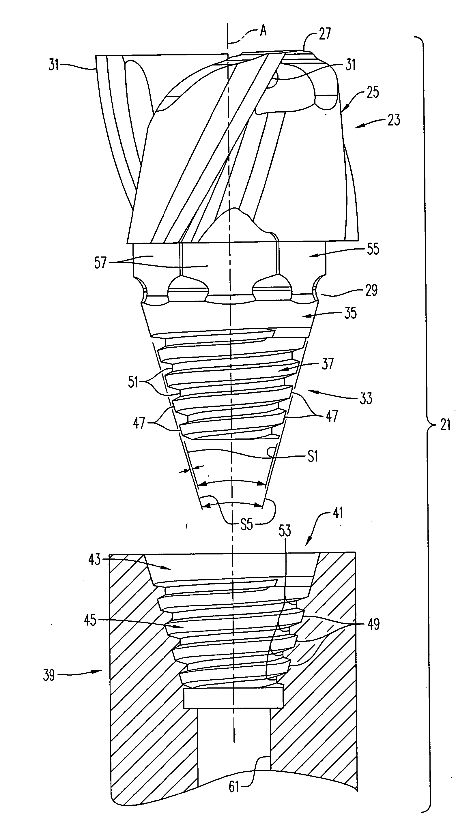
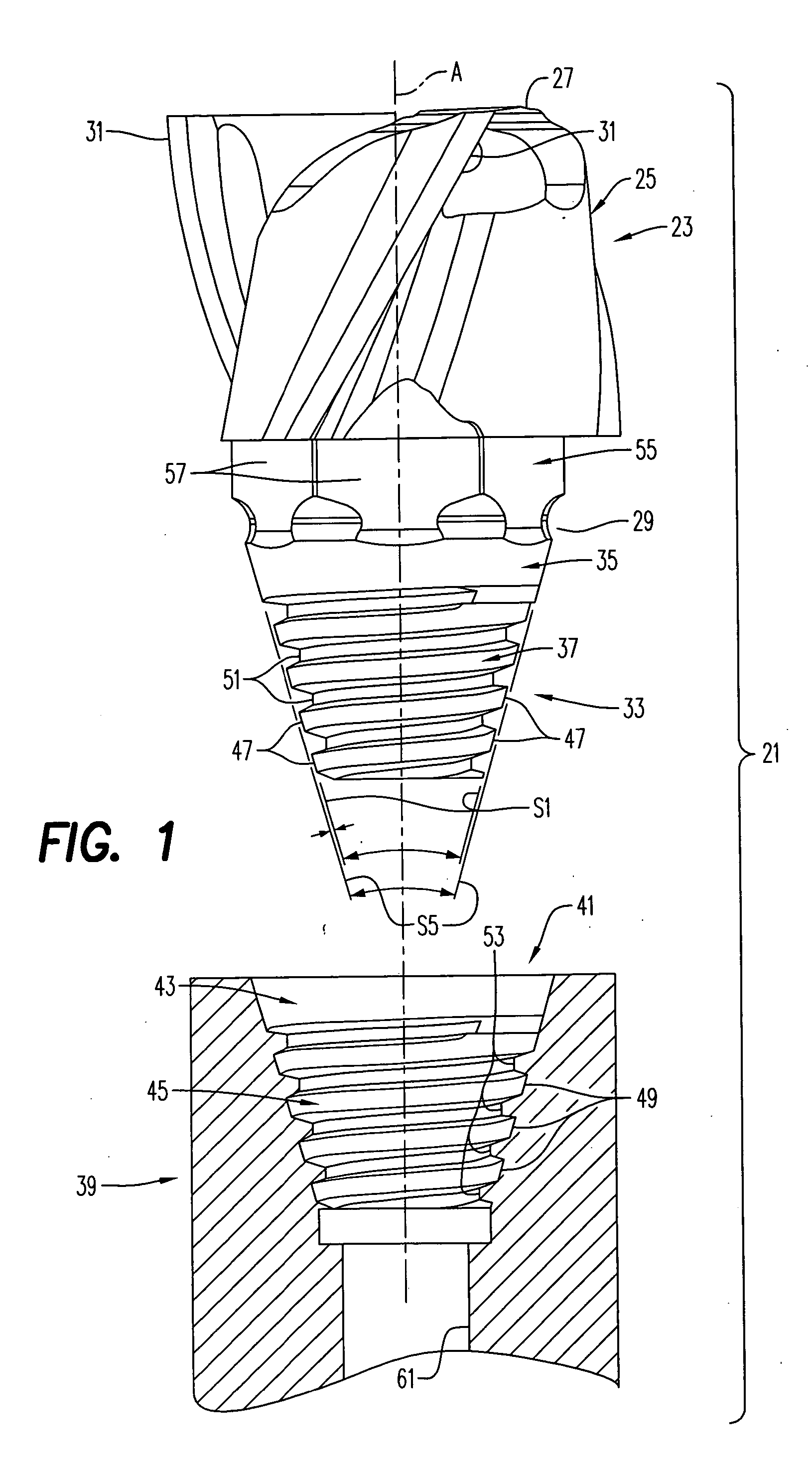
[0019] A cutting tool 21 according to an embodiment of the present invention is shown in FIG. 1. The cutting tool 21 includes a replaceable cutting tip 23 including a working end portion 25 including a first end 27 and a second end 29. The replaceable cutting tip 23 is made of hard material, such as for example cemented carbide, e.g. tungsten carbide (WC) sintered together with cobalt (Co). The replaceable cutting tip 23 is molded or pressed and / or ground. The working end portion 25 is disposed along an axis A of the cutting tip 21 and includes one or more cutting edges 31 proximate the first end 27 for machining a workpiece (not shown). The cutting tip 23 also includes a mounting portion 33 disposed along the axis A of the cutting tool 21. The mounting portion 33 includes a frustoconical supporting surface tip portion 35 and a frustoconical threaded tip portion 37.

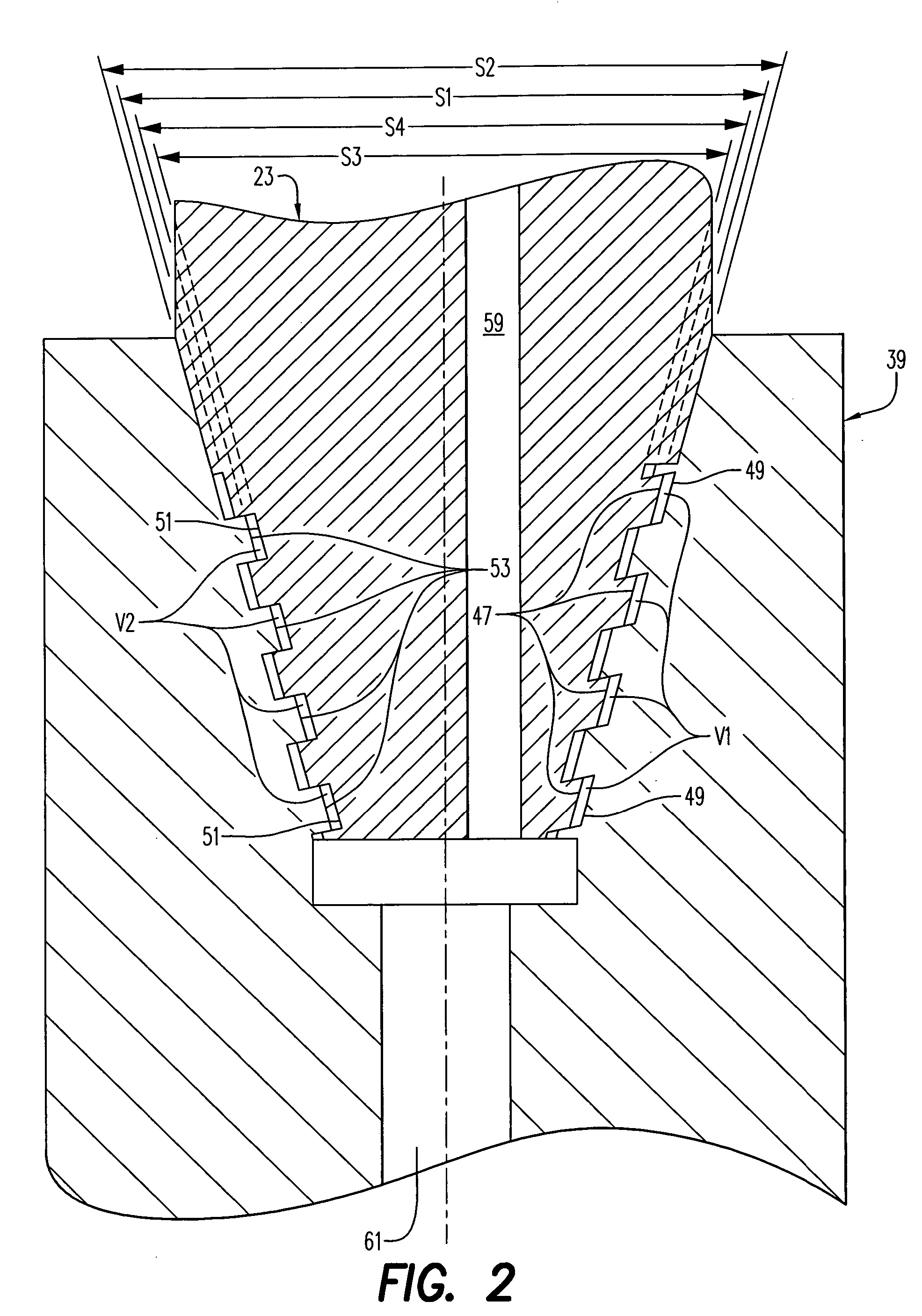
[0020] The cutting tool 21 also includes a cutting tip holder 39. The holder 39 includes a holder mounting portion 41 ...


PUM

PropertyMeasurementUnit
cone angleaaaaaaaaaa
diameteraaaaaaaaaa
cone angleaaaaaaaaaa

Abstract

The present invention relates to a replaceable cutting tip and, more particularly, to such cutting tips attachable to the cutting tip holders by a threaded connection. The cutting tip for a cutting tool includes a working end portion disposed along an axis of the cutting tip and including one or more cutting edges for machining a workpiece, and a mounting portion disposed along the axis of the cutting tip. The mounting portion includes a frustoconical supporting surface tip portion and a frustoconical threaded portion. The present invention also relates to a cutting tool per se.

Description

BACKGROUND AND SUMMARY [0001] The present invention relates to cutting tools including replaceable cutting tips and, more particularly, to such cutting tools with the cutting tips attachable to the cutting tip holders by a threaded connection. [0002] In making threaded connections between two parts, it is possible to permit faster connection of the parts by forming the internal and external threads in a cone or frustoconical shape. In this way, the externally threaded part does not have to be screwed into the internally threaded part from a leading end of the internally threaded part to its final position. Instead, the leading end of the externally threaded part can be inserted into the internally threaded part past internal threads at the leading end of the internally threaded part that define diameters that are larger than the diameter defined by the leading end of the externally threaded part. The leading end of the externally threaded part can be inserted into the internally thr...

Claims


Application Information

Patent Timeline
Patent Type & Authority Applications(United States)
IPC IPC(8): B23B51/00B23BB23B31/11B23C5/10
CPCB23B31/1107B23B31/1115B23C5/10B23C2210/02Y10T408/94Y10T408/90993Y10T407/1946Y10T279/16B23C2210/03B23B51/00B23C5/20
Inventor JONSSON, CHRISTERHOGRELIUS, BENGTERIKSSON, JANEJDERKLINT, CHRISTERBERGLOW, CARL-ERIKKOSKINEN, JORMABOMAN, JONAS
Owner SECO TOOLS AB
Why Eureka
Try Eureka