Linear oscillating pressurizing device

a pressurizing device and oscillating technology, applied in the direction of positive displacement liquid engines, pump types, machines/engines, etc., can solve the problems of easy waste of motor energy, unsuitable for small-volume products, and inability to use devices with pump types, etc., to achieve the effect of reducing the size of such a pressurizing device and low operating noise of the present invention

Inactive Publication Date: 2006-04-06
ROSSMAX INT
View PDF4 Cites 4 Cited by
  • Summary
  • Abstract
  • Description
  • Claims
  • Application Information

AI Technical Summary

Benefits of technology

[0005] The present invention is to provide a linear oscillating pressurizing device that employs a piston element made of permanent magnet and two electromagnetic elements. A series of oscillating current pulse cycle generated from a control circuit can drive the piston element having an air inlet valve to perform reciprocating movement and the air inlet control during the reciprocating movement, so as to complete the pressurizing action.
[0006] The present invention is also to provide a linear oscillating pressurizing device that employs a control circuit to generate a series of current pulses to magnetize the two electromagnetic elements to have the same polarity and to change polarity in response to current pulse cycle. The simultaneous attractive and repulsive forces exerted on the piston element by the two electromagnetic elements double the pressurizing effect.
[0007] The present invention is yet also to provide a linear oscillating pressurizing device that employs a control circuit to generate a series of oscillating current pulse cycle to directly drive the piston element made of permanent magnet and the direction of magnetic forces of the two electromagnetic elements. The size of such a pressurizing device can largely be reduced and applicable to micro devices such as wrist or finger electronic blood pressure meters, or other pressurizing devices. In addition, the operation noise of the present invention is also very low.

Problems solved by technology

In other words, this type of pump can not be used in devices that require high flow volume or high pressure.
However, such shaft transmission structure can easily waste energy output from the motor, especially when changing the moving direction of the shaft.
Therefore, it is not suitable for products of small volume, such as a blood pressure meter, especially a wrist type blood pressure meter or a finger type blood pressure meter.

Method used


Image

  • Linear oscillating pressurizing device
  • Linear oscillating pressurizing device
  • Linear oscillating pressurizing device

Examples


Embodiment Construction

[0013] In order to better understanding the features and technical contents of the present invention, the present invention is hereinafter described in detail by incorporating with the accompanying drawings. However, the accompanying drawings are only for the convenience of illustration and description, no limitation is intended thereto.

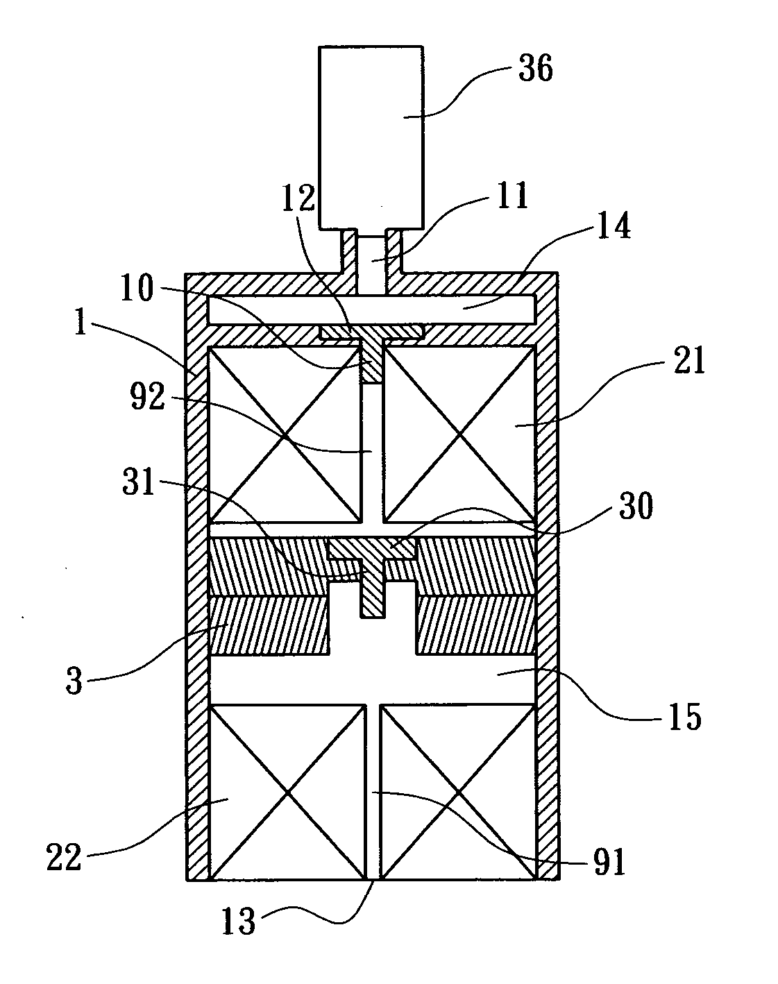
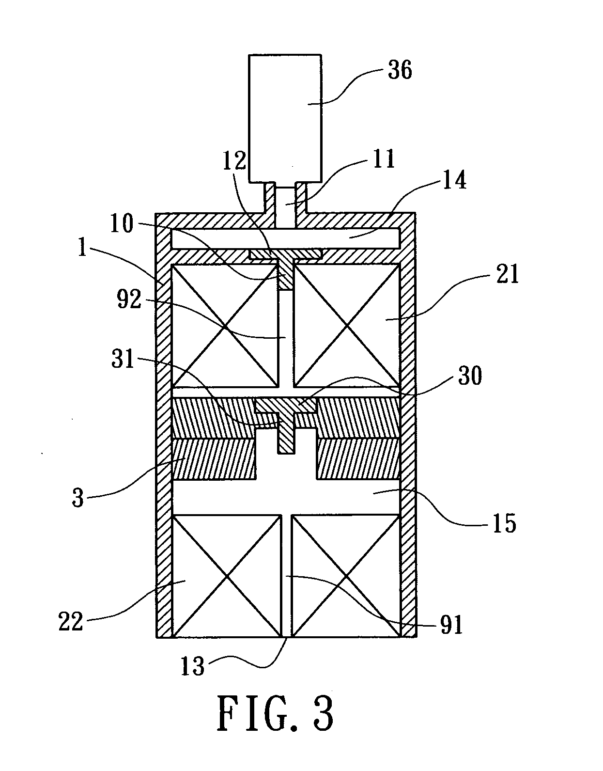
[0014] Referring first to FIG. 3 and FIG. 4, a linear oscillating pressurizing device in accordance with one embodiment of the present invention is illustrated. As shown, the pressurizing device includes: a main body 1 to contain all necessary elements of the present invention; two electromagnetic elements 21, 22 disposed in the main body 1; a piston element 3 disposed between the two electromagnetic elements 21, 22; and a control circuit 4 (not shown) electrically coupling the two electromagnetic elements 21, 22 to control magnetic properties.

[0015] The main body 1 includes an air room 14 and an air chamber 15, thereby defining a hollow space for ...


PUM


Abstract

A linear oscillating pressurizing includes a main body having an air outlet end and an air outlet valve, two electromagnetic elements disposed in the main body, a piston element disposed between the two electromagnetic elements, which has an air inlet valve disposed thereon, and a control circuit to generate oscillating current pulses. By using a series of current pulses generated from the control circuit, one can magnetize the two electromagnetic elements to the same polarity. By changing the polarity of the electromagnetic element, the attractive force and the repulsive force exerted on the piston element doubles the magnetic force used for reciprocating the piston element. By further incorporating the reciprocating movement of the piston element with the air flow, a pressurizing device having a doubled pressurizing output is obtained.

Description

BACKGROUND OF THE INVENTION [0001] The present invention relates generally to a linear oscillating pressurizing device, and more particularly to a linear oscillating pressurizing device that employs a permanent magnetic piston and two electromagnetic element to drive a piston element having an air inlet performing a reciprocating movement via a series of oscillating current pulse generated from a digital control circuit, thereby completing a pressuring action by employing the reciprocating movement of the piston element. [0002] Conventional pressuring devices, such as pumps, or hydraulic or air pressurizing device, add energy or pressure to air or liquid. In general, pumps can be divided into centrifugal pumps and reciprocating pumps. The centrifugal pumps employ rotating blades to perform pressurizing actions, which is suitable for systems of high flow volume, low viscosity and static pressure. [0003] The aforementioned reciprocating pumps are widely used in low flow volume pumping...

Claims


Application Information

Patent Timeline
Patent Type & Authority Applications(United States)
IPC IPC(8): F04B35/04F04B17/04
CPCF04B35/045
Inventor WU, CHAU-CHUANWU, TOWER S.J.
Owner ROSSMAX INT
Why Eureka
Try Eureka