Orbiting vane compressor

a vane compressor and orbiting technology, which is applied in the direction of liquid fuel engines, machines/engines, rotary piston liquid engines, etc., can solve the problems of deteriorating compression performance of the compressor, reducing the volumetric efficiency of the compressor, and the inability to apply the conventional vane compressor, etc., to achieve easy oil supply, improve the compression capacity and performance of the orbiting, and facilitate oil separation

Inactive Publication Date: 2006-04-06
LG ELECTRONICS INC
View PDF6 Cites 9 Cited by
  • Summary
  • Abstract
  • Description
  • Claims
  • Application Information

AI Technical Summary

Benefits of technology

[0015] Therefore, the present invention has been made in view of the above problems, and it is an object of the present invention to provide an orbiting vane compressor having two compression chambers formed in a cylinder according to an orbiting movement of an orbiting vane, thereby improving compression capacity and performance of the orbiting vane compressor as compared to a conventional rotary compressor having a single compression chamber, accomplishing easy oil supply to a compression unit of the orbiting vane compressor, and accomplishing easy separation of oil from discharged gas.

Problems solved by technology

It is impossible, however, to apply the conventional vane compressor with the above-stated construction and operation as a refrigerant compressor used in a refrigerator or an air conditioner.
As a result, the refrigerant gas is introduced into the cylinder in a high-temperature and low-pressure state, which decreases the volumetric efficiency of the compressor.
Consequently, the compression performance of the compressor is deteriorated.
Consequently, it is impossible to increase the sectional area of the refrigerant gas inlet channel, which is necessary to reduce pressure loss.

Method used


Image

  • Orbiting vane compressor
  • Orbiting vane compressor
  • Orbiting vane compressor

Examples


Embodiment Construction

[0041] Now, preferred embodiments of the present invention will be described in detail with reference to the accompanying drawings.

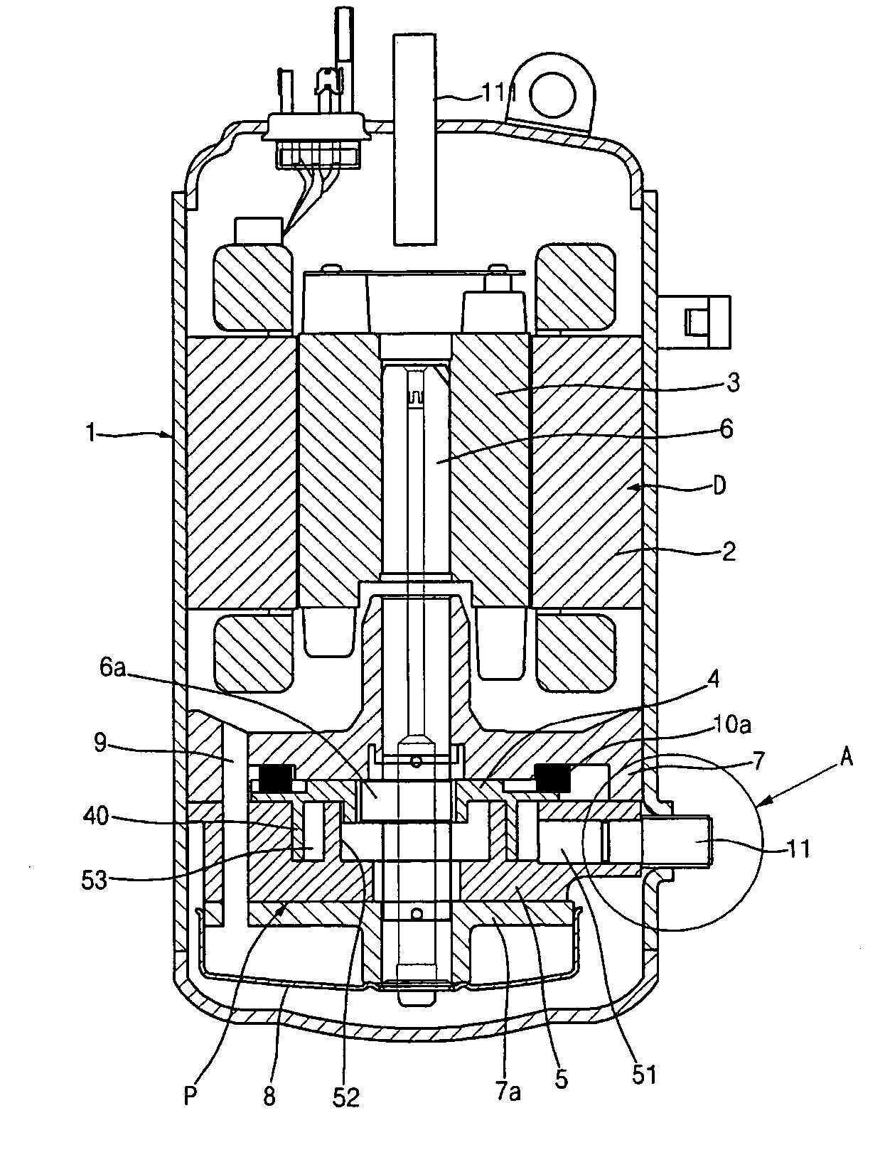
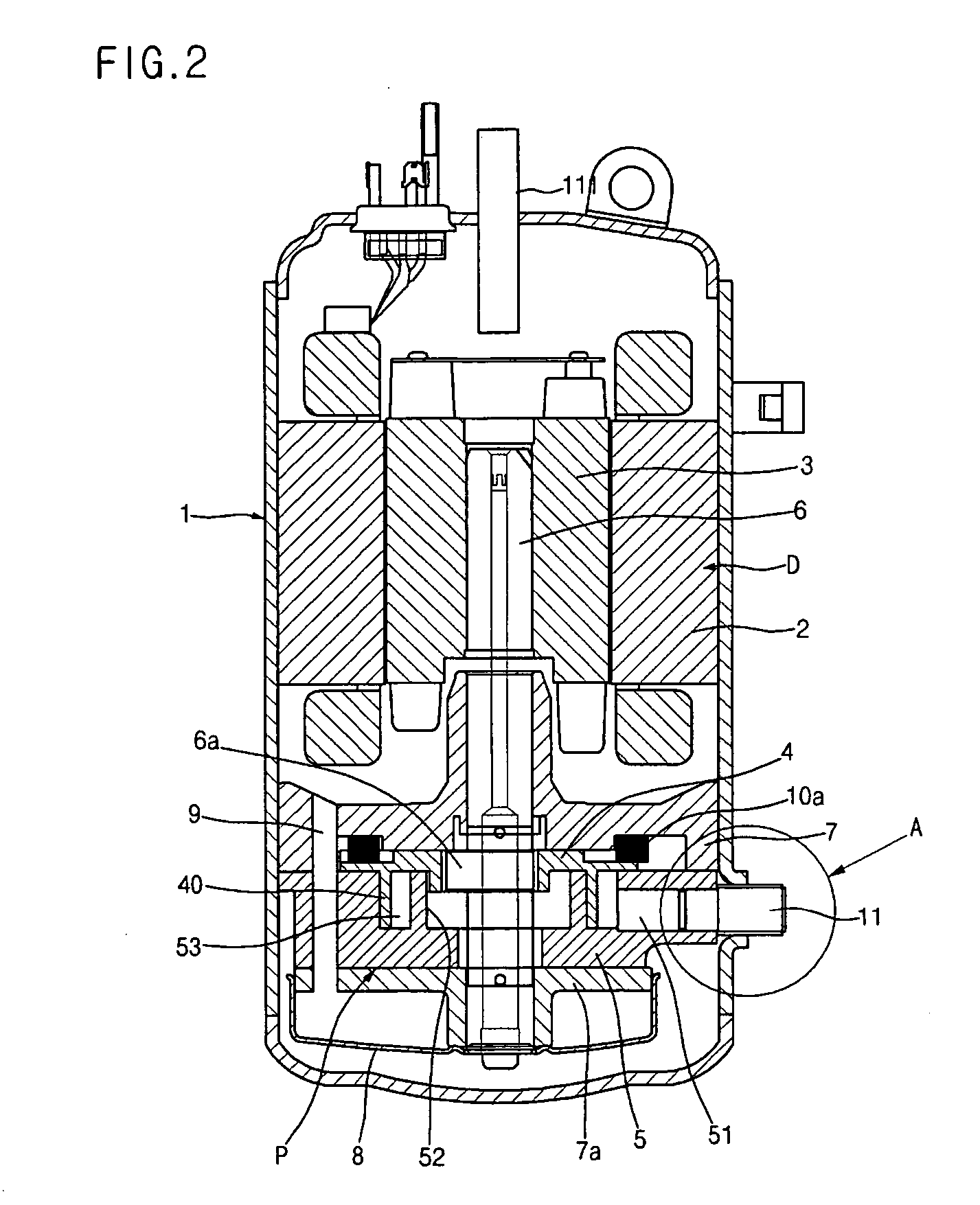
[0042]FIG. 2 is a longitudinal sectional view illustrating the overall structure of a hermetically sealed type orbiting vane compressor according to a first preferred embodiment of the present invention.

[0043] As shown in FIG. 2, a drive unit D and a compression unit P are mounted in a shell 1 while the drive unit D and the compression unit P are hermetically sealed. The drive unit D is disposed in the upper inner part of the shell 1, and the compression unit P is disposed in the lower inner part of the shell 1. The drive unit D and the compression unit P are connected to each other via a vertical rotary shaft 6. The rotary shaft 6 has an eccentric part 6a.

[0044] The drive unit D comprises: a stator 2 fixedly disposed in the shell 1; and a rotor 3 disposed in the stator 2 for rotating the rotary shaft 6, which vertically extends through the rotor 3, w...


PUM


Abstract

Disclosed herein is an orbiting vane compressor having two compression chambers formed in a cylinder according to an orbiting movement of an orbiting vane. The orbiting vane compressor comprises a shell having an inlet tube and an outlet tube, the shell being hermetically sealed such that refrigerant gas is introduced through the inlet tube and is then discharged through the outlet tube, a rotary shaft disposed in the shell while being supported by upper and lower flanges, the rotary shaft being rotated by a drive unit, and a compression unit for compressing refrigerant gas introduced into a cylinder according to an orbiting movement of an orbiting vane, which is attached to the rotary shaft, and discharging the compressed refrigerant gas to the lower part of the cylinder.

Description

BACKGROUND OF THE INVENTION [0001] 1. Field of the Invention [0002] The present invention relates to an orbiting vane compressor, and, more particularly, to an orbiting vane compressor having two compression chambers formed in a cylinder according to an orbiting movement of an orbiting vane, thereby improving compression capacity and performance of the orbiting vane compressor as compared to a conventional rotary compressor having a single compression chamber, accomplishing easy oil supply to a compression unit of the orbiting vane compressor, and accomplishing easy separation of oil from discharged gas. [0003] 2. Description of the Related Art [0004] Generally, a vane compressor compresses air introduced into a cylinder according to an orbiting movement of a vane. FIG. 1 is a longitudinal sectional view illustrating the overall structure of a conventional vane compressor. [0005] As shown in FIG. 1, the vane compressor comprises a compression unit 100 connected to a drive unit (not ...

Claims


Application Information

Patent Timeline
Patent Type & Authority Applications(United States)
IPC IPC(8): F16N13/20F01C20/18F01C1/02F04C2/00
CPCF04C18/02F04C23/008F04C18/045F04C2230/60F04C2240/30F04C2230/20F04C18/344F04C18/356
Inventor HWANG, SEON-WOONGYOO, DONG-WON
Owner LG ELECTRONICS INC
Why Eureka
Try Eureka