
Marine reversing gear assembly

a technology of reversing gear and gear assembly, which is applied in the direction of marine propulsion, vessel construction, propulsive elements, etc., can solve the problems of wasting the marine reversing gear assembly itself or the parts installed, and affecting the operation of the directional control valv

Active Publication Date: 2006-04-06
YANMAR CO LTD
View PDF6 Cites 25 Cited by
  • Summary
  • Abstract
  • Description
  • Claims
  • Application Information

AI Technical Summary

Benefits of technology

The patent text describes a marine reversing gear assembly that allows for the installation of both a manual directional control valve and an electromagnetic directional control valve in the same hydraulic oil supply line. This allows for easy replacement of the valves without the need for costly parts. The assembly also includes a trolling device that can be easily adjusted for different hydraulic oil pressure requirements. The technical effects of this invention include the ability to change the specification of the valves easily, the ability to control the operation of either the manual or electromagnetic directional control valve, and the ability to adapt to complicated oil passages.

Problems solved by technology

However, the electromagnetic directional control valve has drawbacks in that it is susceptible to salt damage by sea water, and the function of the directional control valve tends to be spoiled by electrical shorts in the electrical circuit of the electromagnetic valve or by the malfunction of relay switches.
When such failure arises, the spool of the electromagnetic valve needs to be directly operated by human power, which makes it quite difficult and troublesome to manage crafts.
This results not only in wasting the marine reversing gear assembly itself or the parts installed therein but also requires much work for the replacement.
Therefore, if the hydraulic oil adjustment element is changed from a mechanical element to an electrical element, or vice versa, after the installation thereof, the gear case itself for the trolling device must be replaced, resulting in wasting the hydraulic oil pressure adjusting element installed beforehand requiring much work for the replacement.
In that case, the mechanical or electrical hydraulic oil adjusting device installed beforehand is completely useless.

Method used


Image

  • Marine reversing gear assembly
  • Marine reversing gear assembly
  • Marine reversing gear assembly

Examples


Embodiment Construction

[0092] Hereinafter, a marine reversing gear assembly according to one embodiment of the invention will be described. In all of the figures, the same reference numerals denote the same constitutional elements.

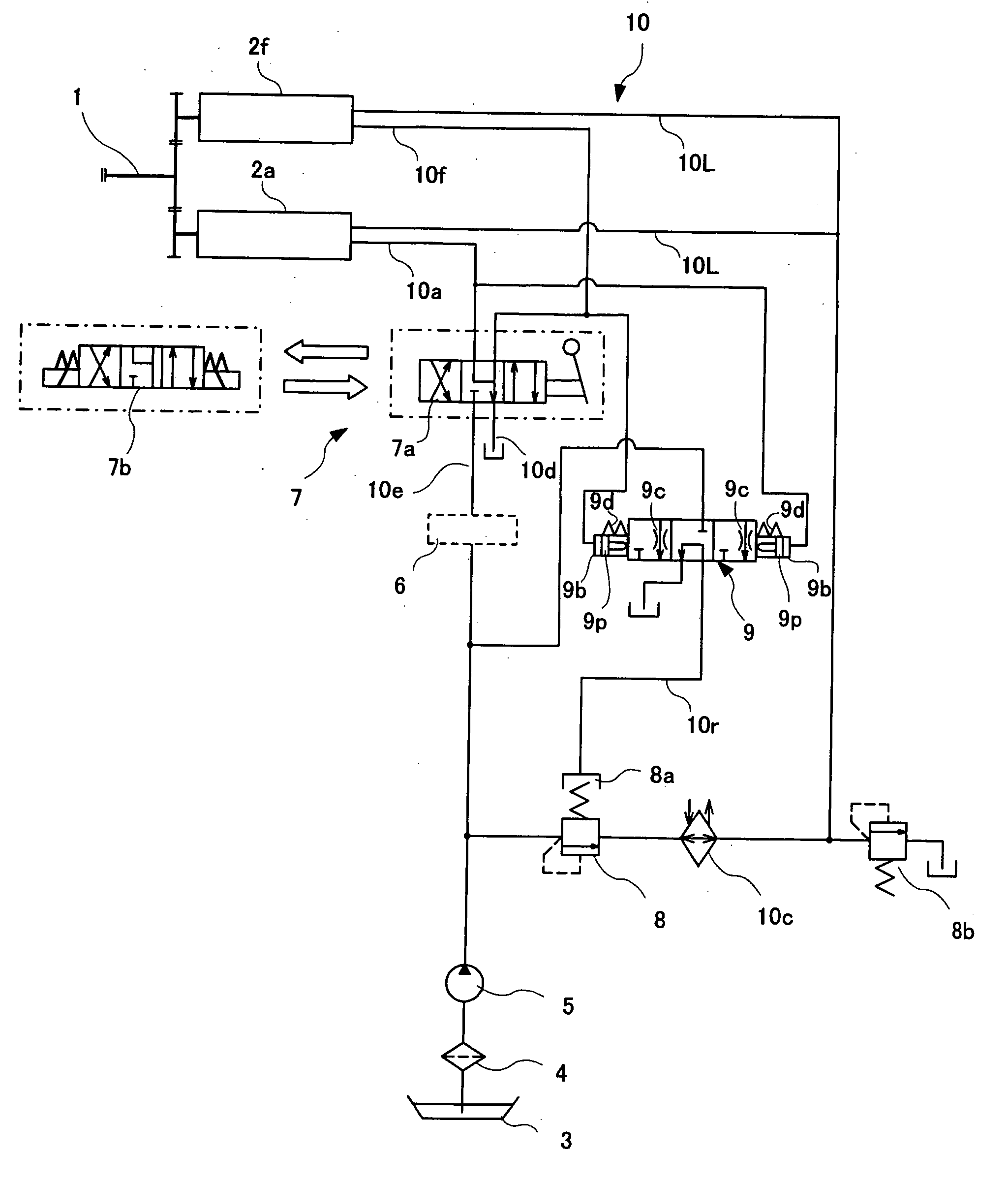
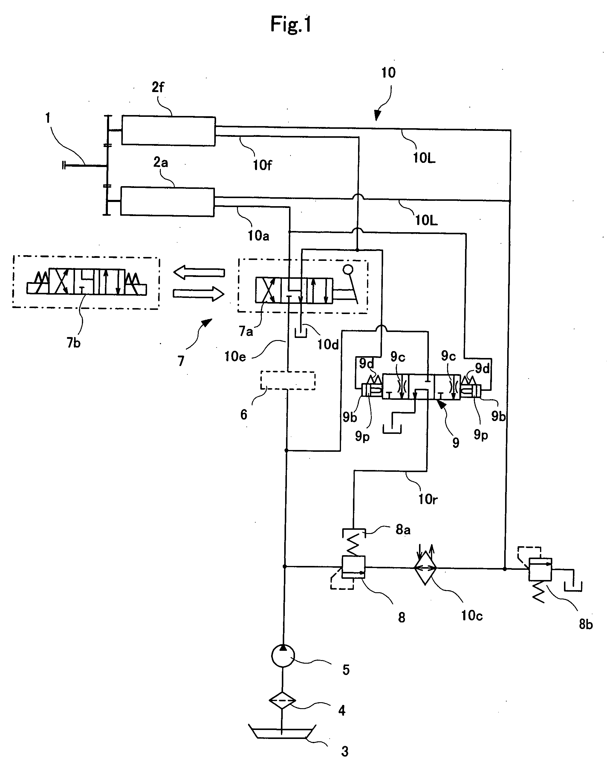
[0093]FIG. 1 is an oil circuit diagram of a marine reversing gear assembly according to this embodiment of the invention. An input shaft 1 that receives drive force from an engine disposed outside the view is provided with a forward clutch 2f and a reverse clutch 2a.

[0094] Although not shown in detail, the forward clutch 2f and the reverse clutch 2a comprise friction discs and steel plates that are disposed alternately. The steel plates are connected to an inside gear, and the friction discs are connected to an outside gear that is in continuous rotation. By pressing the friction discs and steel plates against each other by a hydraulic piston, the outside gear and the inside gear rotate integrally. This rotate a large gear that engages the inside gear, thereby rotating a prope...


PUM


Abstract

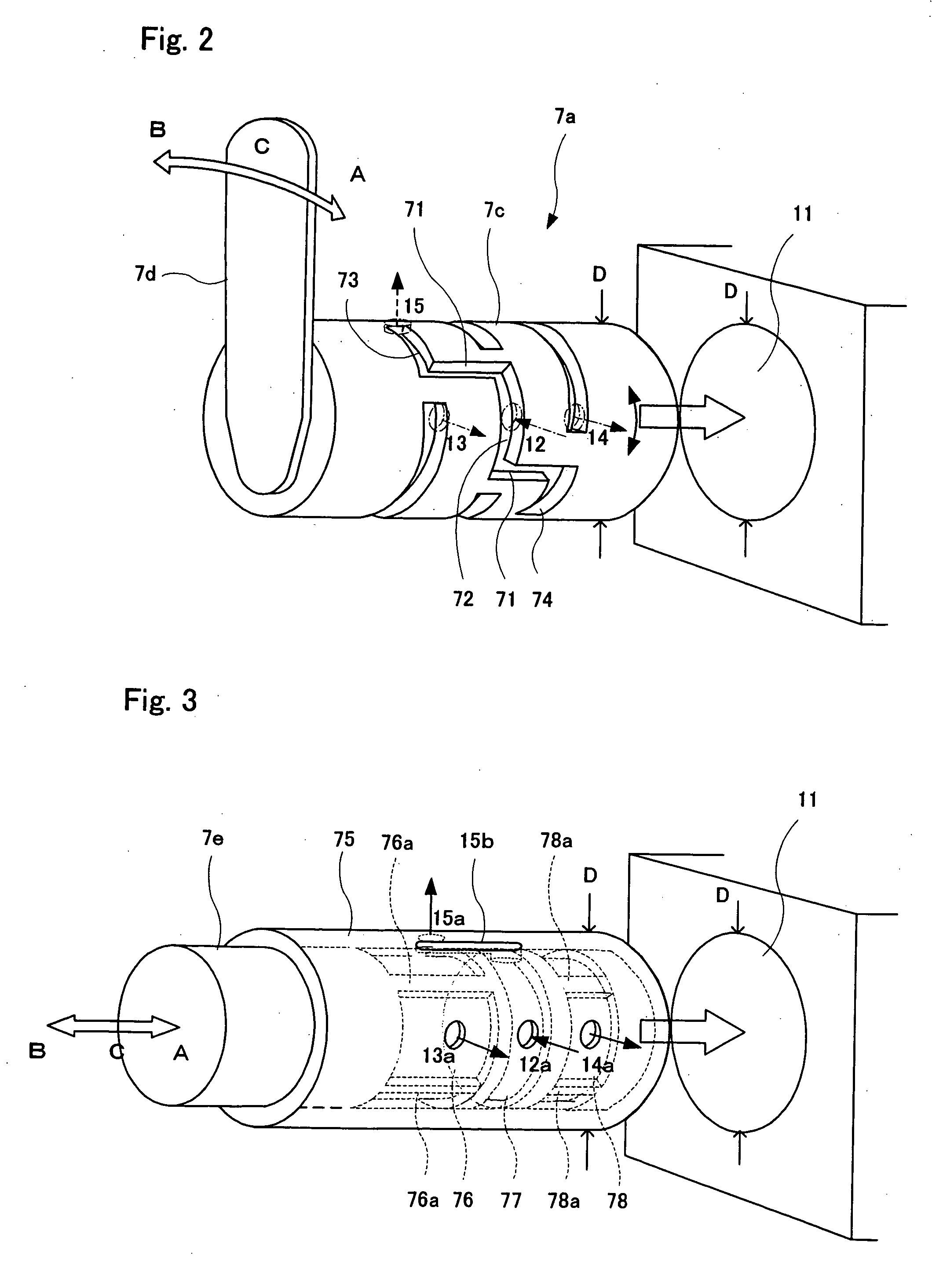
The present invention provides a marine reversing gear assembly, wherein a manual directional control valve 7a and an electromagnetic directional control valve 7b for a forward / reverse directional control valve 7 for hydraulic oil supply circuit 10 have a common structure of an oil line joint surface for the hydraulic oil supply circuit 10 for friction discs of a forward clutch 2f and a reverse clutch 2a, and the forward / reverse directional control valve 7 for the hydraulic oil supply circuit 10 can be changed to either the manual directional control valve 7a or the electromagnetic directional control valve 7b by exchanging spools 7c or 7e of the manual directional control valve 7a or the electromagnetic directional control valve 7b. Therefore, the operational manner of the forward / reverse directional control valve for the hydraulic oil supply line of a marine reversing gear assembly can be changed quite easily between the manual directional control valve and the electromagnetic directional control valve.

Description

BACKGROUND OF THE INVENTION [0001] (1) Field of the Invention [0002] The present invention relates to a marine reversing gear assembly. [0003] (2) Description of the Related Art [0004] Conventionally, a marine reversing gear assembly provided with a friction disk hydraulic clutch is known for use in small crafts, such as motorboats, fishing boats, and the like. Such a marine reversing gear assembly is disclosed in, for example, Japanese Patent Publication No. 1994-80098. [0005] The marine reversing gear assembly is configured in such a manner that hydraulic oil pressure is applied to the friction disks of a forward clutch or a reverse clutch to press the friction disks against each other, and the rotation of an output shaft is transmitted to an input shaft, thereby forwarding and reversing crafts. [0006] There are two means for exchanging the hydraulic oil pressure of the hydraulic clutch according to the forwarding or reversing motions. In one means, a directional control valve for...

Claims


Application Information

Patent Timeline
Patent Type & Authority Applications(United States)
IPC IPC(8): B63H20/14B63H23/00
CPCB63H23/30B63H23/08B63H20/20
Inventor HARADA, KAZUYOSHITERASAWA, YOSHIAKIOGA, NAOYUKIMISAO, HIDEO
Owner YANMAR CO LTD
Learn More