Power transmission device

Active Publication Date: 2006-04-06
KASAHARA FUMIO
View PDF7 Cites 8 Cited by
  • Summary
  • Abstract
  • Description
  • Claims
  • Application Information

AI Technical Summary

Benefits of technology

[0018] According to the power transmission device of the invention, as has been detained hereinbefore, the two sets of planetary gear mechanisms are interposed between the transmission shaft and the turni

Problems solved by technology

According to the power transmission device of the prior art, however, numerous gears and bearings are needed for each of the two transmission lines and the different

Method used


Image

  • Power transmission device
  • Power transmission device
  • Power transmission device

Examples


Example

EMBODIMENT 1

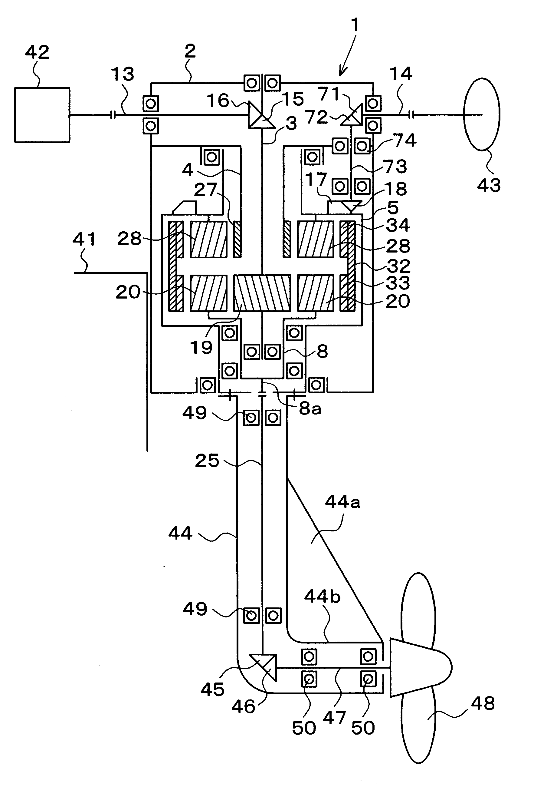
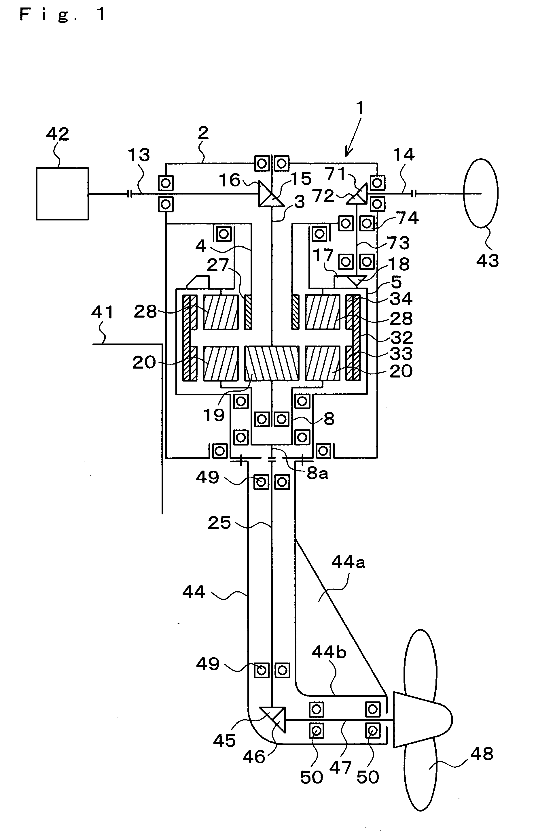
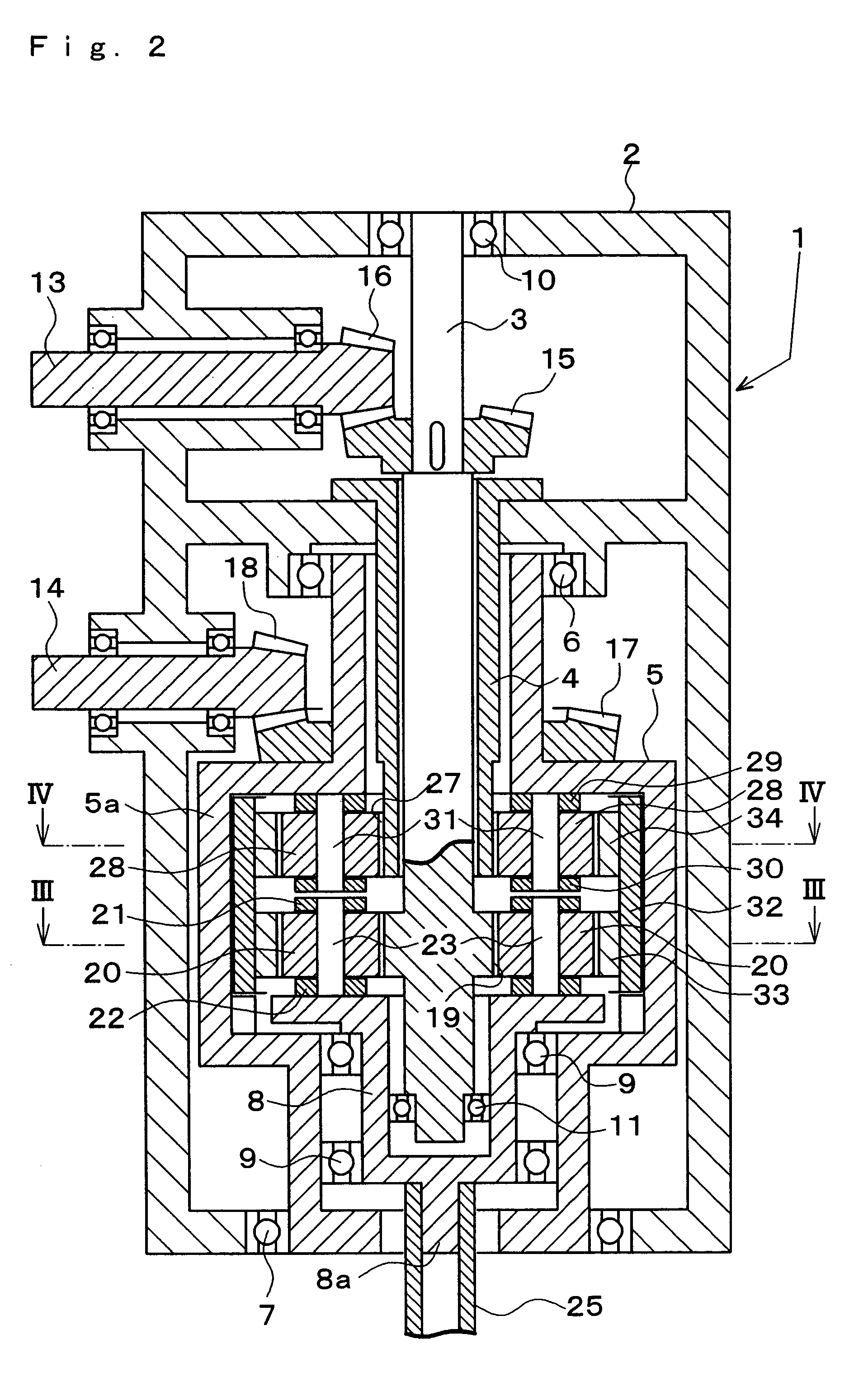
[0038] Embodiments of the invention are described in the following with reference to the accompanying drawings. In a power transmission device 1 of Embodiment 1, as shown in FIG. 1 to FIG. 4, a transmission shaft 3 is disposed at the center of a housing 2, and a turning body 5 is arranged on the outer side of the transmission shaft 3 through a hollow-cylindrical shaft 4. The turning body 5 is supported at the housing 2 by bearings 6 and 7, and a cup-shaped rotating body 8 is supported on the inner side of the lower end portion of the turning body 5 by a bearing 9. The transmission shaft 3 is almost inserted into the inner side of the turning body 5, and has its lower end supported at the rotating body 8 by a bearing 11 and its upper end supported at the housing 2 by a bearing 10. As a result, the transmission shaft 3 and the turning body 5 are supported at the housing 2 so as to be relatively coaxially rotatable. The hollow-cylindrical shaft 4 is inserted into the inner...

Example

EMBODIMENT 2

[0052] Here is described another application example of the power transmission device 1. In this application example shown in FIG. 9, the power transmission device 1 is incorporated into a 2WD motorcycle or bicycle. Accordingly, the power transmission device 1 of Embodiment 2 shown in FIG. 9 is different in the supporting structure of the rotating input shaft 13 and in the input type for turning from the power transmission device 1 of Embodiment 1. Specifically, the transmission shaft 3 protrudes to the outside of the housing 2, and the rotating input shaft 13 is connected to that protruding portion through the bevel gears 15 and 16. The rotating input shaft 13 may or may not be supported by the housing 2. This housing 2 is fixed on a body frame 51; the turning body 5 is mounted on a front wheel fork 52; and the output shaft 25 and a front wheel drive shaft 53 acting as the rotating shaft are supported at the casing 44. The drive force for rotation by the engine or the ...

Example

EMBODIMENT 3

[0054] In an application example shown in FIG. 10, the power transmission device 1 is incorporated into the oscillating mechanism of a wind power generating system. Accordingly, the power transmission device 1 of Embodiment 3 shown in FIG. 10 is different in the following points from the power transmission device 1 of Embodiment 1. Specifically: the housing 2 is fixed on a post 61 in a mode inverted from that of the case of the ship propelling mechanism; the rotating input shaft 13 is connected to an input portion 8b of the rotating body 8; and the output shaft 25 is connected to the lower end of the transmission shaft 3. An oscillating head 62 is so mounted on the turning body 5 through the casing 44 as to turn in all directions; the rotating input shaft 13 is supported at the casing 44; and a propeller shaft 64 is supported at the oscillating head 62 by a bearing 67. The propeller shaft 64 is perpendicularly connected to the rotating input shaft 13 through bevel gears...


PUM


Abstract

Mutual interference between rotation and turning drive forces is prevented by a simple structure. A transmission shaft and a turning body are supported at a housing so as to be relatively coaxially rotatable. An input shaft is connected to the transmission shaft, and a first sun gear is fixed thereon. First planetary gears meshing with the first sun gear are supported at a rotating body, which is connected to an output shaft. A second sun gear is provided on a hollow-cylindrical shaft fixed to the housing. Second planetary gears supported at the turning body mesh with the second sun gear. A first and second inner gears mesh with the first and second planetary gears respectively. They are corotatably connected by a connection ring. A rotating shaft is perpendicularly connected to the output shaft through bevel gears. A casing supporting the output and rotating shafts and is joined to the turning body.

Description

CROSS REFERENCE TO PRIOR APPLICATION [0001] This application is a continuation of International Patent Application Serial No. PCT / JP2004 / 007192, filed May 26, 2004 which claims priority to Japanese Patent Application No. 2003-150328, filed May 28, 2003 which is incorporated by reference herein.TECHNICAL FIELD [0002] The present invention relates to a general-purpose power transmission device for transmitting a power on a turning body. BACKGROUND OF THE INVENTION [0003] Japanese Patent No. 3,012,417 describes a power transmission device for a 2WD (two-wheel drive) motorcycle. This power transmission device is provided with two housings. One housing is fixed on a body frame whereas the other housing is assembled with a front-wheel fork. These two housings are jointed so all-around rotatably that the front wheel can be turned 360 degrees by manipulating a handle. [0004] The housing on the body side is provided with an input shaft whereas the housing on the front wheel side is provided ...

Claims


Application Information

Patent Timeline
IPC IPC(8): F16H57/08B62M11/18B63H20/00B63H23/08F16H1/46
CPCB62M11/18B63H20/12B63H20/16B63H23/14B63H2020/005B63H2023/0283B63H2023/062B63H2023/065F16H1/46
Inventor KASAHARA, FUMIO
Owner KASAHARA FUMIO
Why Eureka
Try Eureka