

Quartz crystal element made of double-rotation y-cut quartz crystal plate
- Summary
- Abstract
- Description
- Claims
- Application Information
AI Technical Summary
Benefits of technology
Problems solved by technology
Method used
Image

Examples
first embodiment
[0040]FIG. 7 shows a quartz crystal element made of a double-rotation Y-cut plate according to the present invention. Particularly, FIG. 7 illustrates a quartz crystal blank constituting the crystal element. Here, description will be made on the case in which the double-rotation Y-cut plate is an SC-cut quartz plate.
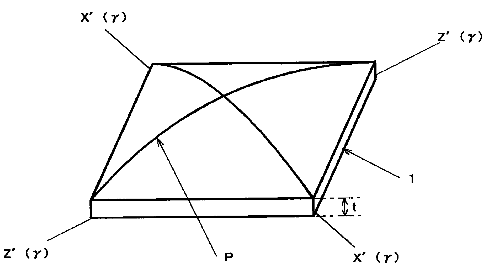
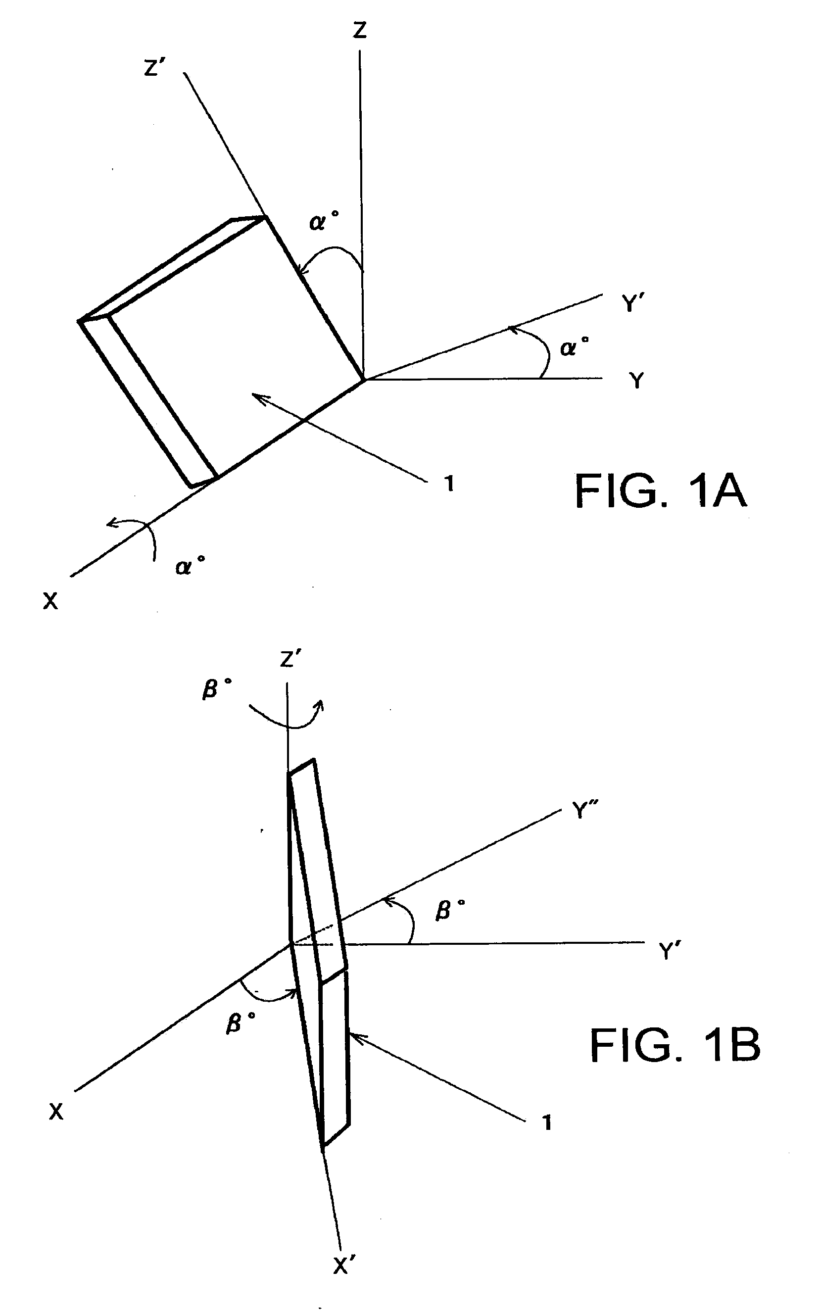
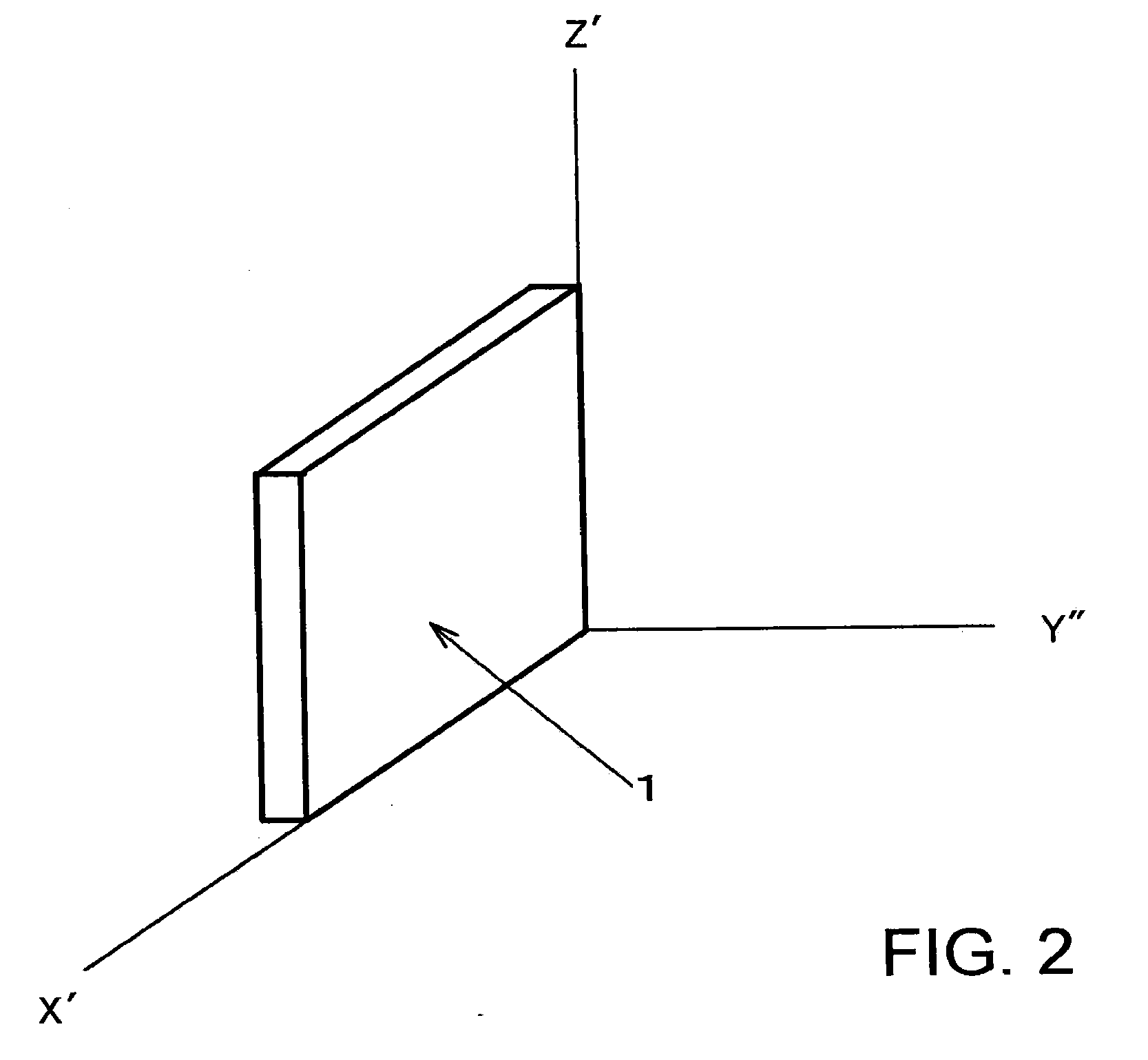
[0041]The SC-cut crystal element uses crystal blank 1 which has a principal plane orthogonal to a Y″-axis, where the Y-axis is rotated twice with rotation angles (reference angles) α and β from the crystallographic X-axis and Z-axis of quartz being 22 degrees and 33 degrees, respectively, and resulting three axes are designated as an X′-axis, a Y″-axis, and a Z′-axis (see FIG. 2). Crystal blank 1 here is configured to have a square planar shape as well, so that diagonal lines which are inclined by an angle of γ from the Z′-axis and the X′-axis, respectively, are null stress-sensitivity axes Z′(γ) and X′(γ). Where γ is 8 degrees.
[0042]In this embodiment, one principal pla...
second embodiment
[0051]Further, by processing one principal plane of crystal blank 1 into a quadrangular pyramid like shape with the thickness of crystal blank 1 being slightly larger than the thickness corresponding to a standard value for target frequency, and thereafter processing vertex portion 5 of the quadrangular pyramid to be a flat surface shape thereby decreasing the thickness of crystal blank 1, it is possible to adjust the vibration frequency of crystal blank 1 in a range of the standard value of the target frequency. Such adjustment of vibration frequency may be performed in a similar fashion in a second embodiment described later.
[0052]FIG. 12A shows a crystal element made of a double-rotation Y-cut plate according to a second embodiment of the present invention. Here, description will be made on the case in which the double-rotation Y-cut plate is an SC-cut plate. FIG. 12A shows a crystal blank in such SC-cut crystal element. In the figure, like components as in the above described ea...
PUM
 Abstract
Description
Claims
Application Information