Minimizing channel change time for IP video

a channel change and video technology, applied in the field of minimizing channel change time for ip video, can solve the problems of putting a strain on the network bandwidth, affecting the quality of ip video, and the prediction from one frame to the next would get progressively worse, so as to reduce the delay, and reduce the delay of channel changing

Inactive Publication Date: 2006-04-06
ENABLENCE USA FTTX NETWORKS
View PDF98 Cites 280 Cited by
  • Summary
  • Abstract
  • Description
  • Claims
  • Application Information

AI Technical Summary

Benefits of technology

[0020] The invention can reduce the delay that occurs when subscribers change channels while watching digital video delivered over broadband Internet Protocol (IP) networks. Specifically, the invention can reduce the channel changing delay when subscribers of the network “channel surf,” or activate a remote control to scroll through or quickly tune through channels in a serial manner to determine what they want to watch. The invention can reduce the channel changing delay by caching video packets for the most likely next channel in a buffer in anticipation of the subscriber changing channels and by having an adaptable buffer length in the set top box.
[0025] For another exemplary aspect of the invention, the invention may be simplified by pre-caching only one I-frame in the customer premise equipment. When the user changes the channel, the single I-frame can then be supplied to the set top box. At that time, a normal IGMP join request can be transmitted upstream to locate the full program stream, while the single I-frame can be captured by the set top box. Each time an I-frame is received, it can be captured and replace the previous I-frame in the cache. Other data not related to the I-frame (such as B- and P-frames) can be discarded. In this alternative exemplary embodiment, the set top box decoder can capture and display that single I-frame as a still picture, until it begins receiving a full MPEG video stream for the selected channel. This can afford the subscriber a quick preview of the channel without requiring significant memory, and it can also simplify the transfer of picture content from the buffer in the customer premise equipment to going directly to the set top box.
[0026] For another exemplary aspect of the invention, the invention can reduce channel change time by using an adaptive buffer length in the set top box. The buffer in the set top box can comprise a first-in-first-out memory (FIFO), which serves to delay all packets arriving at the set top box by some length of time chosen by the set top box manufacturer. This buffer is usually needed in order to prevent momentary picture “freezes,” which can occur if for some reason a packet is delayed in getting to the set top box. However, different video delivery systems exhibit widely varied packet delay times; therefore, set top box manufacturers typically provide a buffer that is long enough to prevent picture freezes under the most severe conditions of packet delay variation.
[0027] In order to reduce the channel change time, data entering the FIFO buffer from the customer premise equipment can enter via a switch which is set to different positions by logic, depending on how long a buffer is needed. The switch can have a position where the buffer length is maximum, and the time required for a video signal to propagate through the buffer is maximum. Therefore, in this position, the channel change time will be maximum. Furthermore, at the opposite extreme, the switch can have a position where the buffer length is minimum, where the channel change time would be minimized because the new channel I-frame would propagate through the buffer in less time. Finally, the switch can have intermediate positions that allow the buffer size to be increased or decreased to certain lengths without reaching the maximum or minimum buffer length.

Problems solved by technology

First, the I-frame usually must be transmitted every so often because if it was not, the prediction from one frame to the next would get progressively worse until the IPTV encoder 220 was transmitting so much predictive error information the picture would not be adequate.
In the alternative, because I-frames require so much data, transmitting too many of them could put a strain on the network bandwidth.
However, subscribers to IPTV services complain about one key characteristic—the additional time delay digital video introduces when subscribers change channels, especially when subscribers desire to “channel surf.” The architecture of the conventional IP video system introduces at least three sources of time delay.
The aggregate of these three sources can create time delays of up to three seconds to change the channel.
One source of delay relates to the common practice of IPTV encoder manufacturers to transmit an I-frame about twice every second as discussed above.
This delay can be one source of irritation to a subscriber, especially if the subscriber is attempting to rapidly scan through channels (“channel surfing”).
Another source of delay relates to the “jitter buffer” that occurs in a buffer found in the STB 270 decoder.
However, the FIFO shift register typically does not begin to transmitting the frames to the STB 270 decoder until the buffer is halfway full, causing a second time delay.
Finally, another source of delay that can occur in a conventional IPTV video system is illustrated in FIG. 2 above.

Method used


Image

  • Minimizing channel change time for IP video
  • Minimizing channel change time for IP video
  • Minimizing channel change time for IP video

Examples


Embodiment Construction

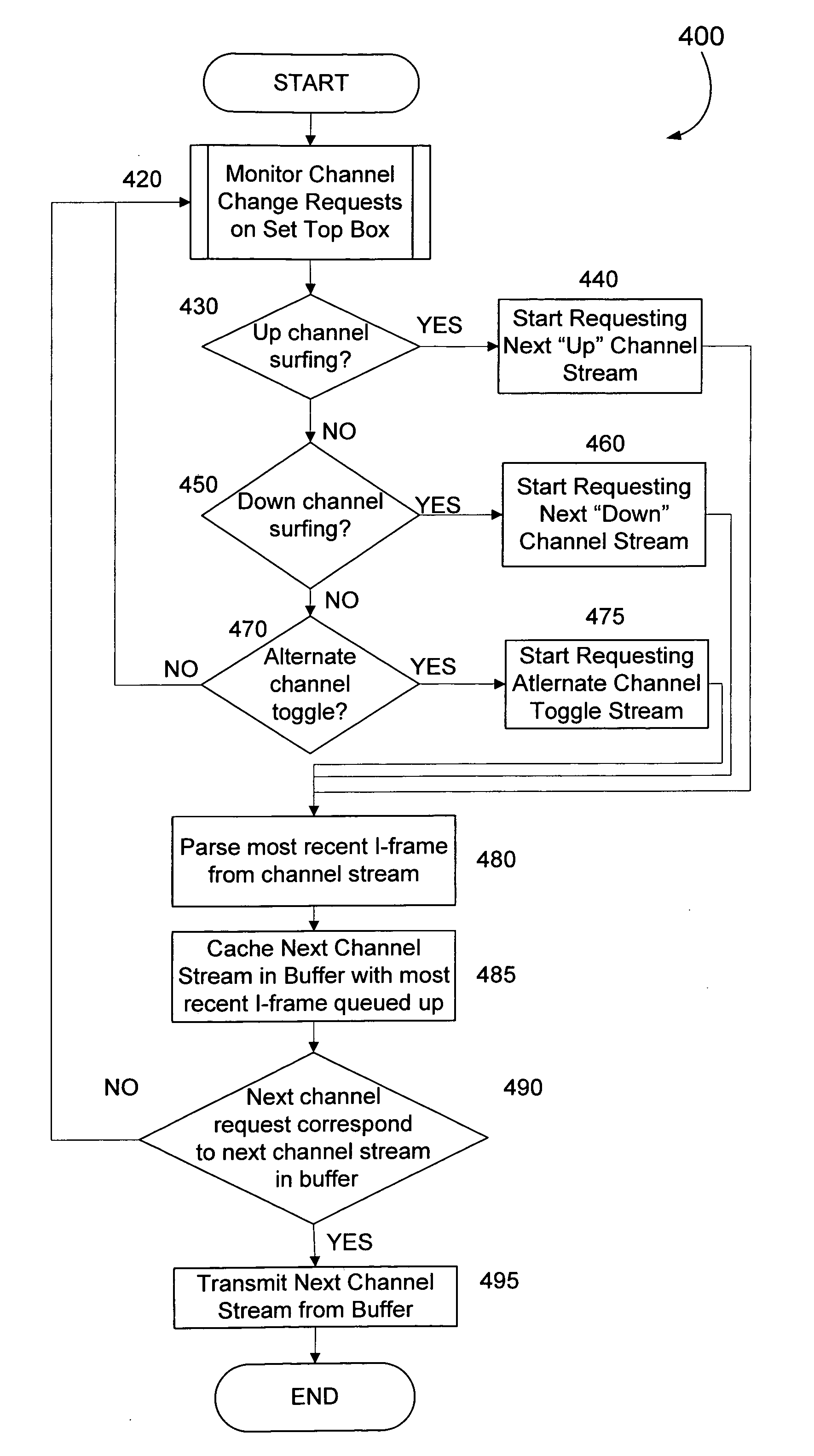
[0042] The invention relates to minimizing the delay that occurs when subscribers change channels while watching digital video delivered over broadband Internet Protocol (IP) networks. Specifically, the invention relates to reducing the channel changing delay when subscribers “channel surf.” The invention can reduce the channel changing delay by caching video packets for the most likely next channel in a buffer in anticipation of the subscriber changing channels and by having an adaptable buffer length in the set top box.

[0043] The description of the flow charts in this detailed description are represented largely in terms of processes and symbolic representations of operations by conventional computer components, including a processing unit (a processor), memory storage devices, connected display devices, and input devices. Furthermore, these processes and operations may utilize conventional discrete hardware components or other computer components in a heterogeneous distributed c...


PUM


Abstract

Subscribers to Internet Protocol TV services usually complain about one key characteristic—the additional delay digital video introduces when subscribers change channels, especially when subscribers “channel surf.” The problem is traced to at least three sources of delay in a convention Internet Protocol video deployment system. The channel changing delay can be minimized by caching video packets for the most likely next channel in a buffer in anticipation of a television subscriber changing channels and / or by having an adaptable buffer length in the set top box.

Description

RELATED APPLICATIONS [0001] The present application claims priority under 35 U.S.C. § 119(e) to provisional patent application entitled, “MINIMIZING CHANNEL CHANGE TIME FOR IP VIDEO,” filed on Oct. 4, 2004, and assigned U.S. Application Ser. No. 60 / 615,856; the entire contents of which are hereby incorporated by reference.FIELD OF THE INVENTION [0002] The invention relates to techniques than can be used to minimize the channel change time for Internet Protocol (IP) Video. More particularly described, the invention can reduce the channel changing delay by caching video packets for the most likely next channel in a buffer in anticipation of a television subscriber changing channels and by having an adaptable buffer length in the set top box. BACKGROUND OF THE INVENTION [0003] In the conventional art, video is typically sent via radio-frequency (RF) broadcast. The broadcast method has been used by off-air television stations, cable television systems, and satellite broadcasters, since ...

Claims


Application Information

Patent Timeline
Patent Type & Authority Applications(United States)
IPC IPC(8): H04N5/445H04N5/50H04N5/00H04N5/44
CPCH04N5/4401H04N5/50H04N7/17336H04N21/4331H04N21/4383H04N21/4384H04N21/44004H04N21/44222H04N21/4667H04N21/6125H04N21/6405H04N21/64322H04N21/8453H04N21/426
Inventor FARMER, JAMES O.THOMAS, STEPHEN A.
Owner ENABLENCE USA FTTX NETWORKS
Why Eureka
Try Eureka