Ultrasonic in-process monitoring and feedback of resistance spot weld quality

Inactive Publication Date: 2006-04-13
CHRYSLER GROUP LLC +1
View PDF10 Cites 81 Cited by
  • Summary
  • Abstract
  • Description
  • Claims
  • Application Information

AI Technical Summary

Benefits of technology

[0019]FIG. 7 is a pair of graphs showing a time of flight for good quality weld, comparing actual results

Problems solved by technology

However, this method only gives information about one side of the weld, telling nothing about the opposite side.
Also, as weld electrodes must be frequently change

Method used


Image

  • Ultrasonic in-process monitoring and feedback of resistance spot weld quality
  • Ultrasonic in-process monitoring and feedback of resistance spot weld quality
  • Ultrasonic in-process monitoring and feedback of resistance spot weld quality

Examples


Embodiment Construction

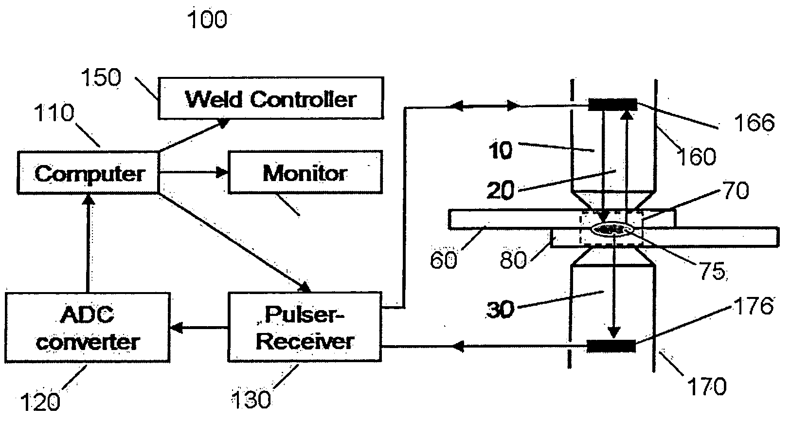
[0020] Referring to FIG. 1, an apparatus 100 for ultrasonic in-process monitoring and feedback according to the invention includes a computer 110, analog-digital converter (ADC) 120, pulser-receiver 130, monitor 140, weld controller 150 and acoustic transmitter-receiver probes 166, 176 mounted within weld electrodes 160, 170.

[0021] Each of the electrodes 160, 170 includes a probe 166, 176 capable of emitting and receiving acoustic waves 10, 20 and 30. The computer 110 sends commands to the weld controller 150 and the pulser-receiver 130. The weld controller 150 clamps the electrodes 160, 170 and starts welding. Simultaneously, the pulser-receiver 130 sends electrical pulses to a probe 166 located in one of the electrodes. The electrical energy is converted into mechanical energy in the form of acoustic waves 10.

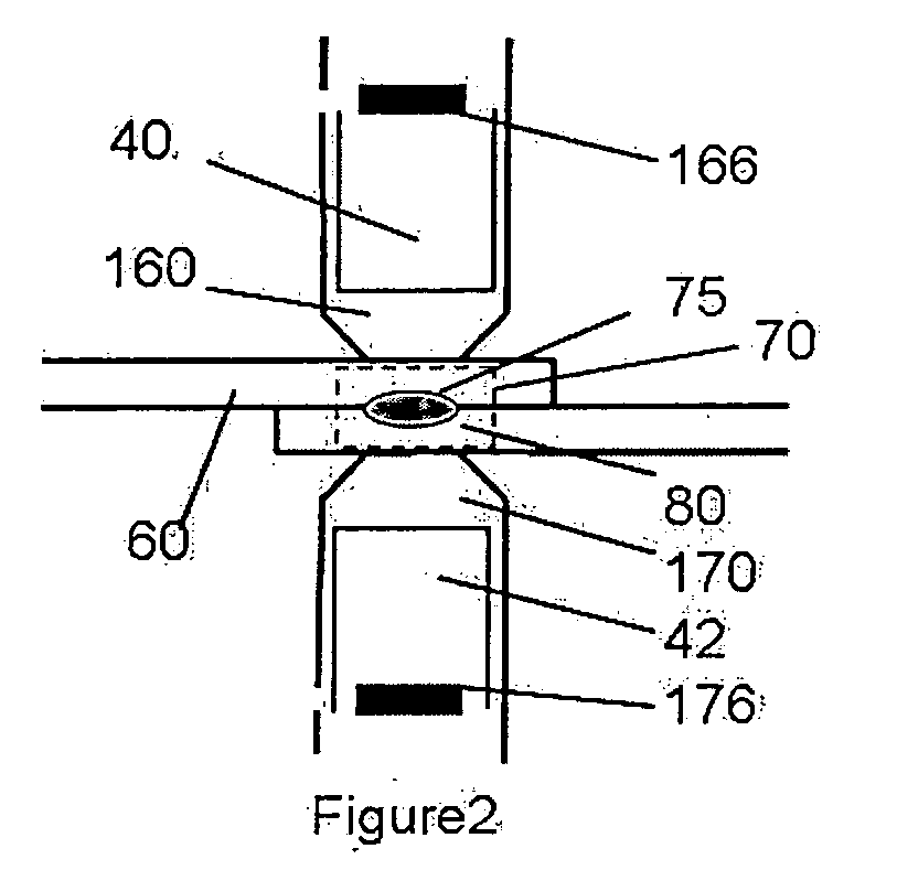
[0022] The waves 10 propagate through the first and second metal layers 60, 80 and the weld zone 70 as long as the metal is transparent to sound waves. The weld zone 70 inc...


PUM

PropertyMeasurementUnit
Temperatureaaaaaaaaaa
Timeaaaaaaaaaa
Thicknessaaaaaaaaaa

Abstract

A method and apparatus for ultrasonic in-process monitoring and feedback of resistance spot weld quality uses at least one transducer located in the electrode assembly transmitting through a weld tip into an underway weld. Analysis of the spectrum of ultrasonic waves provides the operator with an indication of the size, thickness, location, dynamics of formation and quality of the spot weld. The method presents a fundamentally new physical approach to the characterization of the spot weld quality. Together with transmission mode it includes new modes of operation of ultrasonic probes such as a reflection mode and simultaneous use of transmission and reflection modes, and a new physical interpretation of the signal analysis results.

Description

CROSS-REFERENCE TO RELATED APPLICATIONS [0001] This application claims the benefit of U.S. Provisional Patent Application 60 / 614,572, filed Sep. 30, 2004.STATEMENT REGARDING FEDERALLY SPONSORED RESEARCH [0002] Not applicable. BACKGROUND OF THE INVENTION [0003] 1. Field of the Invention [0004] The present invention relates to an ultrasonic transducer associated with an electrode for real-time monitoring and feedback in a welding process. [0005] 2. Description of Related Art [0006] The nondestructive testing of spot welds in real time using ultrasound has many advantages over other nondestructive approaches. Prior art arrangements include the insertion of the ultrasonic probe into the weld electrodes, with the acoustic energy sent through the weld subject. Then the analysis of the transmitted and / or reflected signal is performed in order to make some conclusions about the quality of the weld. [0007] U.S. Pat. No. 3,726,130 discloses a probe glued to the back surface of the welding ele...

Claims


Application Information

Patent Timeline
IPC IPC(8): B23K11/24
CPCB23K11/252B23K20/10B23K31/12G01N29/07G01N29/223G01N29/343G01N2291/0251G01N2291/02854G01N2291/02863G01N2291/0422G01N2291/044G01N2291/101G01N2291/102G01N2291/2672B23K11/25G01N29/06
Inventor MAEV, ROMAN GR.CHERTOV, ANDRIY M.PAILLE, JOHN M.EWASYSHYN, FRANK J.
Owner CHRYSLER GROUP LLC
Why Eureka
Try Eureka