
System for controlling an OLED display

a technology of display device and control system, which is applied in the direction of static indicating device, instruments, etc., can solve the problems of differential color aging and display, less efficient light emission, and reduced display life, so as to reduce light emission efficiency and simple implementation

Inactive Publication Date: 2006-04-13
EASTMAN KODAK CO
View PDF5 Cites 80 Cited by
  • Summary
  • Abstract
  • Description
  • Claims
  • Application Information

AI Technical Summary

Benefits of technology

[0031] The advantages of this invention are systems and methods for operating an OLED device to compensate for reduced light emitting efficiency over time that accommodates manufacturing variability and provides a simple implementation.

Problems solved by technology

However, as the display is used, the organic materials in the device age and become less efficient at emitting light thereby reducing the lifetime of the display.
The differing organic materials may age at different rates, causing differential color aging and a display whose white point varies as the display is used.
Such methods require the integration of optical sensors, greatly increases complexity, and reduces yields in a display.
This approach has the disadvantage of assuming that the behavior of the proxy element is identical to that of the OLED itself.
However, through experimentation, applicant has determined that such measures are inadequate to reliably compensate for the aging of an OLED device.
Moreover, the additional circuitry necessary to measure the instantaneous current for each pixel is complex and error-prone.
This requires extensive timing, calculation, and storage circuitry in the controller.
Also, this technique does not accommodate differences in behavior of the display at varying levels of brightness and temperature and cannot accommodate differential aging rates of the different organic materials.
Alternatively, the instantaneous current-voltage characteristic of a pixel within a display may be monitored, requiring additional circuitry on the display device itself, thereby increasing display complexity and reducing yields.
While such proposed system takes into account operational temperature of the OLED in calculating rate of degradation, similar as with U.S. Pat. No. 6,414,661 B1, the requirement of current integrated charge measurements requires additional circuitry, thereby increasing display complexity and reducing yields.
However, the need for an additional image forming device raises costs and complexity.
The described system requires complex variable power circuitry, however, does not accommodate aging variations due to: environmental conditions, does not account for increased aging that may be associated with employing a corrected input signal, and does not address initial non-uniformity issues, in particular pixels which may be stuck on or stuck off.
Since displays are typically viewed in a single-stimulus environment, slow changes over time are acceptable, but large, noticeable changes are objectionable.
Since continuous, real-time corrections are usually not practical because they interfere with the operation of the OLED display, most changes in OLED display compensation are done periodically.
Hence, if an OLED display output changes significantly during a single period, a noticeably objectionable correction to the appearance of the display may result.
OLED devices are known to decay very quickly when first used.
As time goes by, the decrease in efficiency slows.
While this is useful in correcting the initial performance of an OLED device, it does not provide means for correcting increasing device inefficiency over time.
OLED devices often suffer from non-uniformities between pixels in a multi-pixel device.
Such non-uniformity is attributable to a lack of control and manufacturing and can affect electronic elements and organic materials and coatings in the OLED devices.
However, unless periodic recalibration is performed, such techniques do not compensate for OLED device aging or manufacturing variability.
It is also true that in any real system, measurement anomalies may occur due to environmental or system perturbations or noise that do not reflect the actual situation.
Corrections in response to such anomalies are undesirable and may result in damage to the system or may degrade display performance.
Manufacturing processes used to make OLED displays also exhibit variability that affects the performance of the display and this manufacturing variability needs to be accommodated in any practical aging correction method.
It is difficult to accommodate all environmental factors in a correction scheme.
The methods shown in the prior art do not address these environmental variables.

Method used


Image

  • System for controlling an OLED display
  • System for controlling an OLED display
  • System for controlling an OLED display

Examples


Embodiment Construction

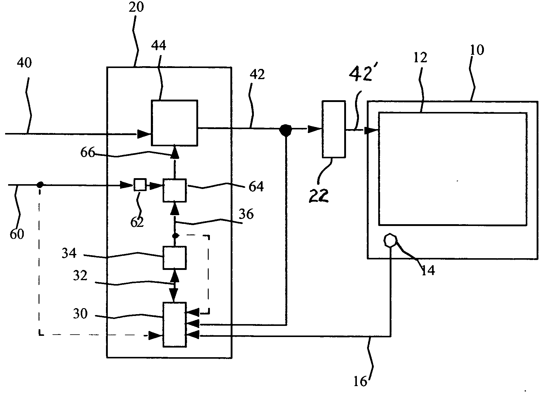
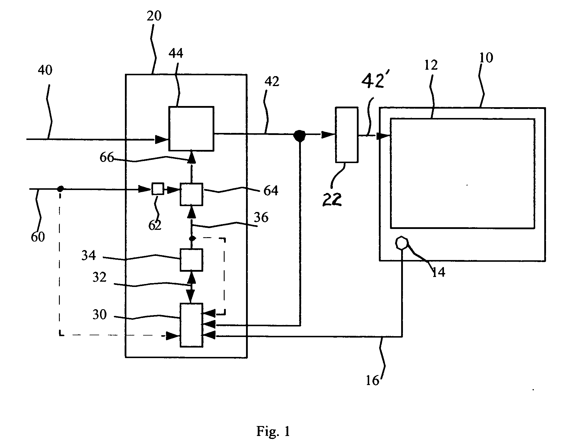
[0036] Referring to FIG. 1, a system for controlling an OLED device having an output that changes with time or use comprises an OLED device 10 responsive to a corrected digital input signal 42 having an array of one or more light emitting elements 12 and a temperature sensor 14 for sensing the temperature of the OLED device 10 and producing a temperature signal 16; a controller 20 including: a first calculation circuit 30 responsive to the temperature signal 16, the digital corrected input signal 42, and a pre-determined aging function to produce a digital aging value 32 corresponding to the aging of the light emitting elements; an accumulation circuit 34 for integrating the digital aging value 32 over time to provide a digital accumulated aging value 36; a storage circuit 62 responsive to a uniformity correction signal 60; a second calculation circuit 64 responsive to the storage circuit 62 and the digital accumulated aging value 36 for calculating a digital correction signal 66; a...


PUM


Abstract

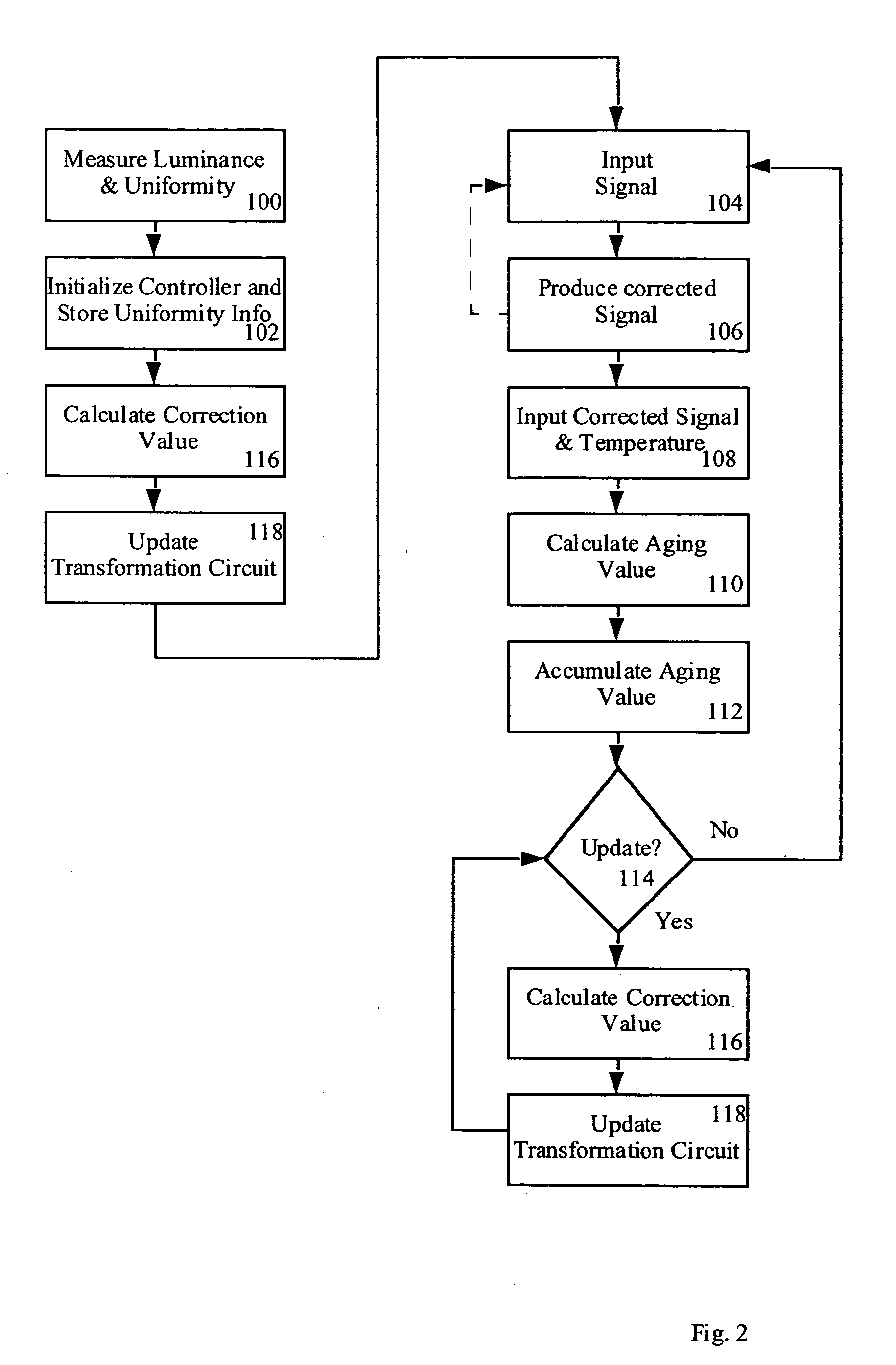
A system for controlling an OLED device having an output that changes with time or use is described, comprising: a) an OLED device responsive to a corrected input signal having one or more light emitting elements and a temperature sensor for sensing the temperature of the OLED device to produce a temperature signal; b) a controller including: i) a first calculation circuit responsive to the temperature signal, a corrected digital input signal, and a pre-determined aging function to produce a digital aging value corresponding to the aging of the light emitting elements; ii) an accumulation circuit for integrating the digital aging value over time to provide a digital accumulated aging value; iii) a second calculation circuit responsive to the digital accumulated aging value for calculating a digital correction signal; and iv) a transformation circuit responsive to a digital input signal and the digital correction signal for transforming the digital input signal to the corrected digital input signal.

Description

FIELD OF THE INVENTION [0001] The present invention relates to solid-state OLED flat-panel display devices and more particularly to systems and methods for controlling an OLED device having an output that changes with time or use to compensate for the aging of the organic light emitting display. BACKGROUND OF THE INVENTION [0002] Solid-state organic light emitting diode (OLED) image display devices are of great interest as a superior flat-panel display technology. These displays utilize current passing through thin films of organic material to generate light. The color of light emitted and the efficiency of the energy conversion from current to light are determined by the composition of the organic thin-film material. Different organic materials emit different colors of light. However, as the display is used, the organic materials in the device age and become less efficient at emitting light thereby reducing the lifetime of the display. The differing organic materials may age at dif...

Claims


Application Information

Patent Timeline
Patent Type & Authority Applications(United States)
IPC IPC(8): G09G3/30
CPCG09G3/3216G09G3/3225G09G2320/0233G09G2320/0285G09G2320/029G09G2320/041G09G2320/043G09G2320/048G09G2320/0666G09G2320/0693G09G2360/145
Inventor COK, RONALD S.
Owner EASTMAN KODAK CO
Learn More