Image processing device and electronic camera

Inactive Publication Date: 2006-04-13
OLYMPUS CORP
View PDF0 Cites 7 Cited by
  • Summary
  • Abstract
  • Description
  • Claims
  • Application Information

AI Technical Summary

Benefits of technology

[0013] According to the present invention, there is provided an image processing device comprising a detecting section (detection unit, detection circuit or the like) which detects blurring of an image (movement of the image) picked up by an imaging element, wherein evaluation data of the picked-up image is calculated (simplified calculation) to obtain an intermediate value (simplified evaluation data) in parallel with a detecting operation of the detecting section, and the result is

Problems solved by technology

However, in the method of Japanese Patent Application Publication No. 06-46311, no processing is performed co

Method used


Image

  • Image processing device and electronic camera
  • Image processing device and electronic camera
  • Image processing device and electronic camera

Examples


Embodiment Construction

[0038] Preferred embodiments of the invention are described below with reference to the accompanying drawings.

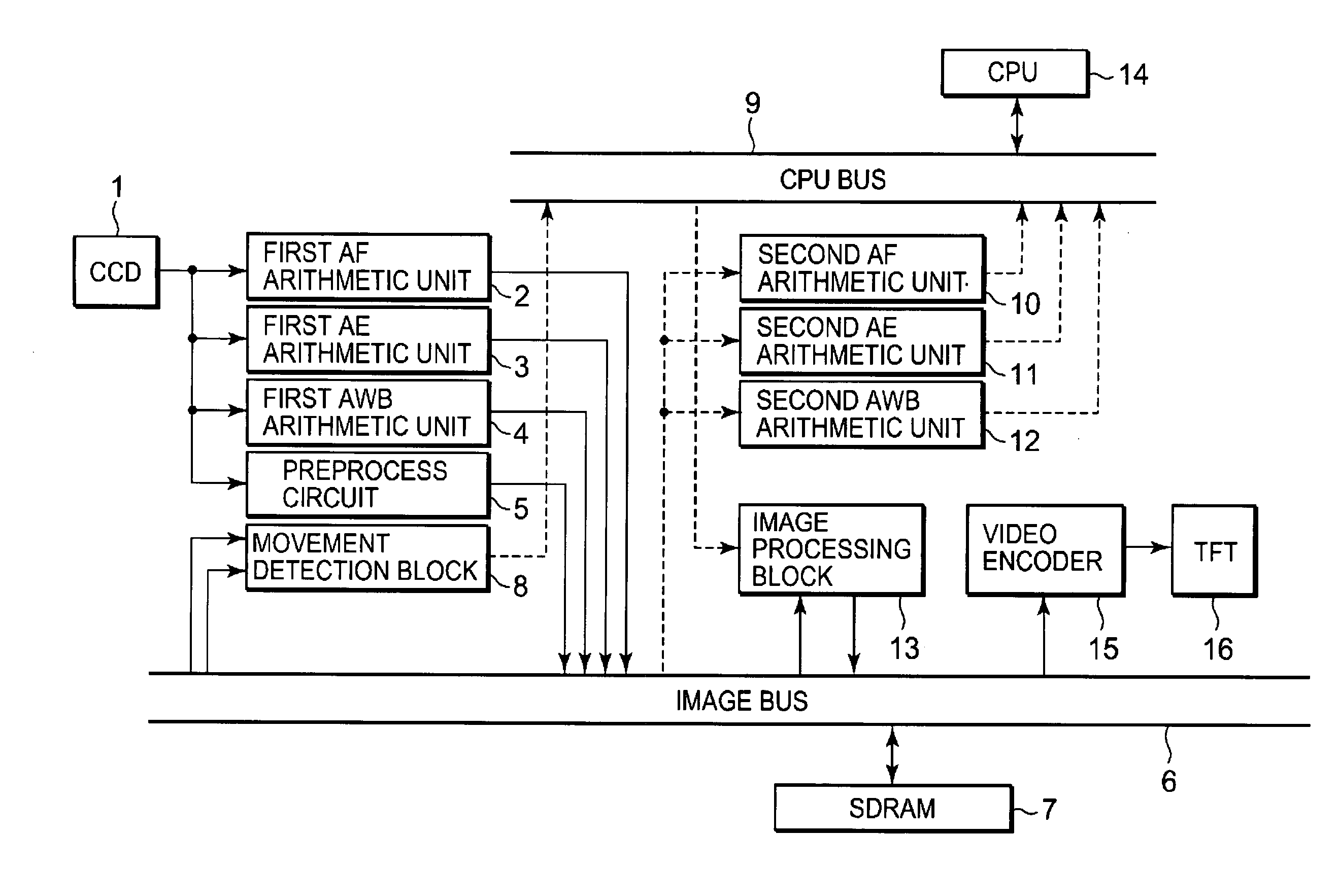
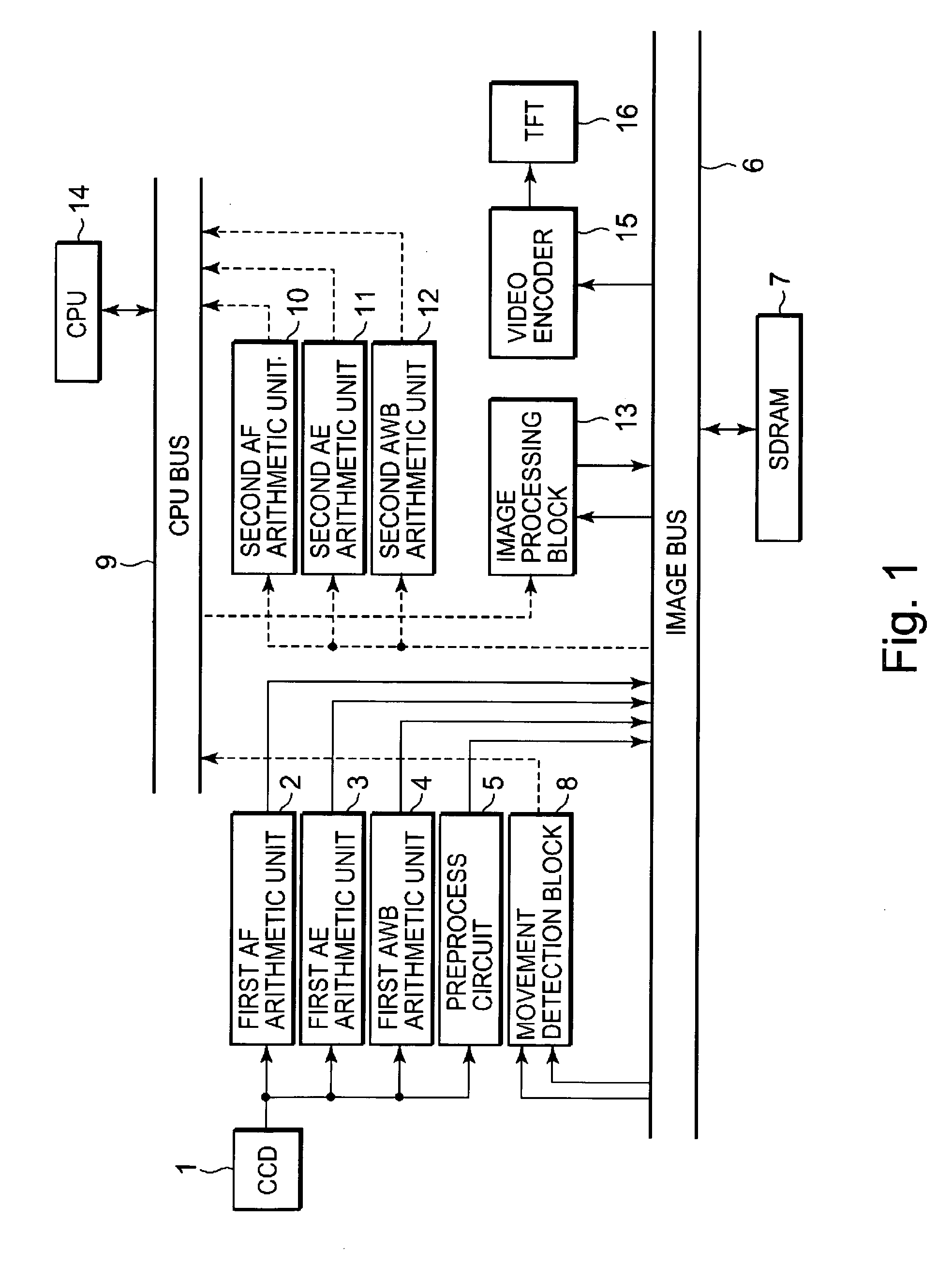
[0039]FIG. 1 is a circuit constitution diagram of an electronic camera on which an image processing device is mounted according to an embodiment of the present invention. That is, the electronic camera of FIG. 1 has: an imaging element (CCD) 1; a first auto focus (AF) arithmetic unit 2; a first auto exposure (AE) arithmetic unit 3; a first auto white balance (AWB) arithmetic unit 4; a preprocess circuit 5; an image bus 6 (which transmits image data); a synchronous DRAM (SDRAM) 7; and a movement detection block 8. The electronic camera further has: a CPU bus 9; a second AF arithmetic unit 10; a second AE arithmetic unit 11; a second AWB arithmetic unit 12; an image processing block 13; a CPU 14; a video encoder 15; and a thin film transistor (TFT) display unit 16. These constitutions may be configured into one chip or several separate units.

[0040] An operation of the electr...


PUM


Abstract

In an image processing device such as an electronic camera having a detecting section which detects blurring of an image (movement of the image) picked up by an imaging element, a part of evaluation or calculation required for controls (AF, AE, AWB, etc.) is performed in parallel with the detection of the blurring of the image in order to speed up the controls. After completing the detection of the image blurring, an influence of the blurring is corrected to perform final calculation. In this case, an image area as a calculation object can be limited to raise a processing efficiency.

Description

CROSS-REFERENCE TO RELATED APPLICATION [0001] This application is based upon and claims the benefit of priority from prior Japanese Patent Application No. 2004-299198, filed Oct. 13, 2004, the entire contents of which are incorporated herein by reference. BACKGROUND OF THE INVENTION [0002] 1. Field of the Invention [0003] The present invention relates to an image processing device and an electronic camera, more particularly to an image processing device and an electronic camera having a function such as vibration correction which detects a movement amount of an image. [0004] 2. Description of the Related Art [0005] There have been proposed various electronic cameras having a so-called electronic vibration correcting function for correcting blurring of an image generated by hands movement or the like by use of the image obtained as digital data. In electronic vibration correction, a little broader image is acquired beforehand in consideration of movement of the image by the hands mov...

Claims


Application Information

Patent Timeline
IPC IPC(8): H04N5/228
CPCH04N5/23248H04N5/23254H04N5/23258H04N5/23267H04N5/23274H04N23/68H04N23/6811H04N23/6812H04N23/683H04N23/6842
Inventor TANAKA, YOSHINOBUUENO, AKIRAYANADA, TAKASHI
Owner OLYMPUS CORP
Why Eureka
Try Eureka