Method of visually inspecting turbine blades and optical inspection system therefor

a technology of optical inspection and turbine blades, which is applied in the direction of instruments, machines/engines, mechanical equipment, etc., can solve the problems of tens of millions of dollars each, serious damage and possible injury to the blades, and achieve the effect of maximizing the amount of blades

Inactive Publication Date: 2006-04-13
SIEMENS ENERGY INC
View PDF16 Cites 93 Cited by
  • Summary
  • Abstract
  • Description
  • Claims
  • Application Information

AI Technical Summary

Benefits of technology

[0017] The viewing device may be an optical passage structured to maximize the amount of the blade which can be viewed through the inspection port, the optical passage including a first end, a second end and an intermediate portion therebetween wherein the first end of the optical passage is coupled to the inspection port and the imager is c

Problems solved by technology

Gas and steam turbines for electrical power generation are very expensive (i.e., tens of millions of dollars each).
However, defects in the blades of large turbines can cause serious damage and possibly injury.
Disassembling a turbine to inspect it is an expensive process and takes the turbine out of service for a significant amount of time.
Unfortunately, none of the foregoing techniques are suitable for inspection while the turbine is on-line and running under load.
Unfortunately, each of the foregoing inspection methods and apparatus has its own unique set of disadvantages.
The interior environment of a turbine is an extremely hostile environment for electrical equipmen

Method used


Image

  • Method of visually inspecting turbine blades and optical inspection system therefor
  • Method of visually inspecting turbine blades and optical inspection system therefor
  • Method of visually inspecting turbine blades and optical inspection system therefor

Examples


Embodiment Construction

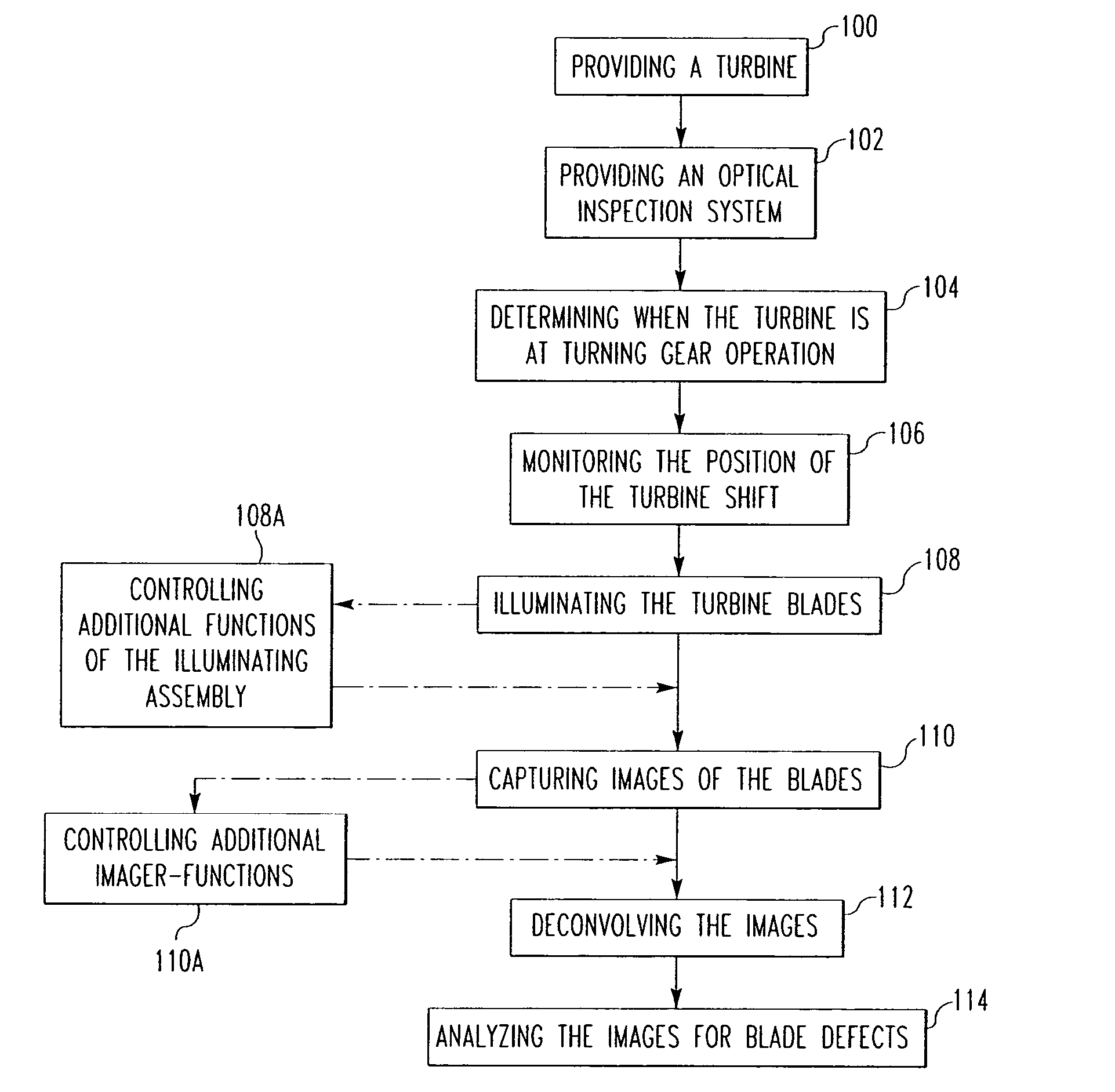
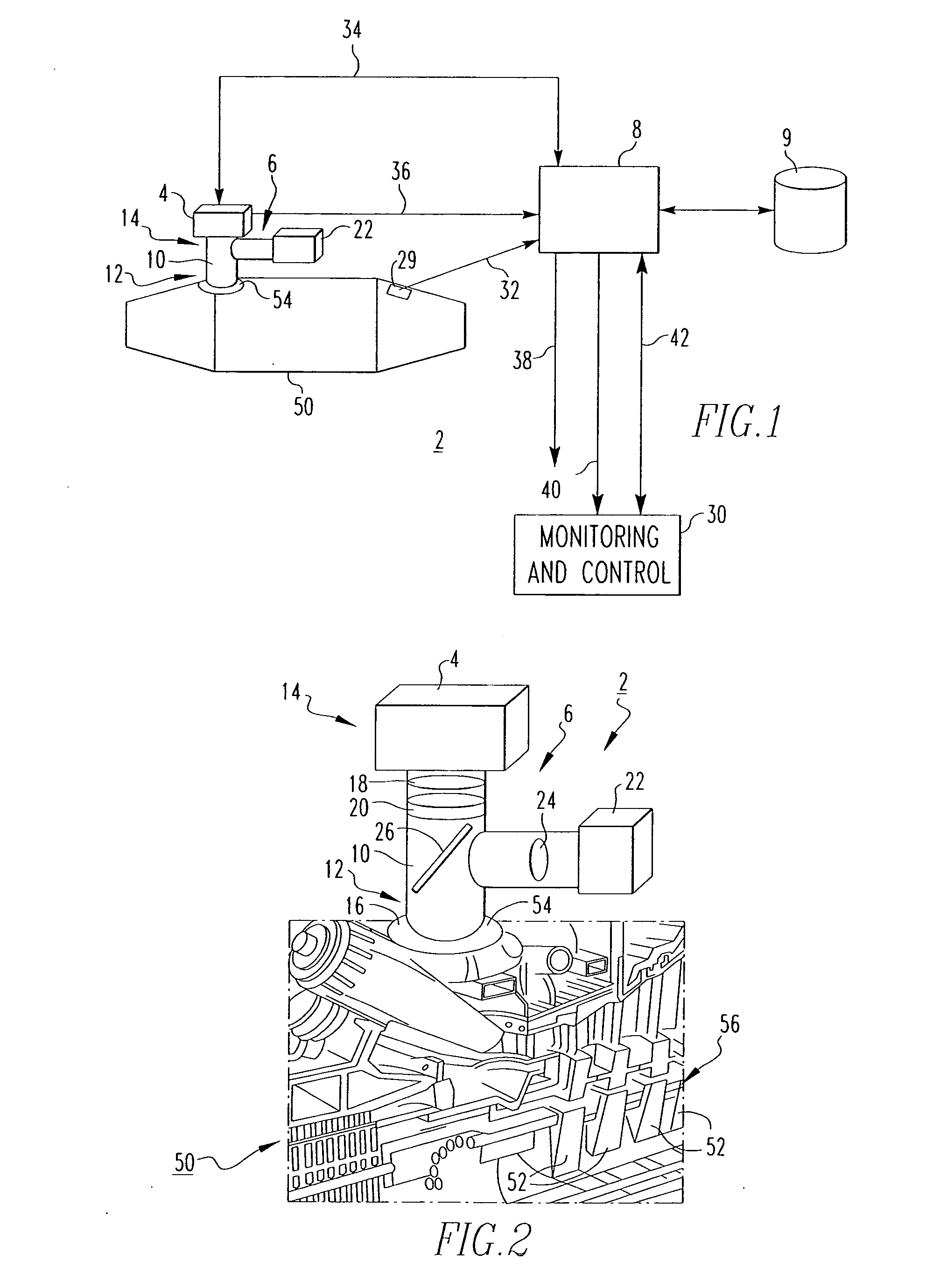
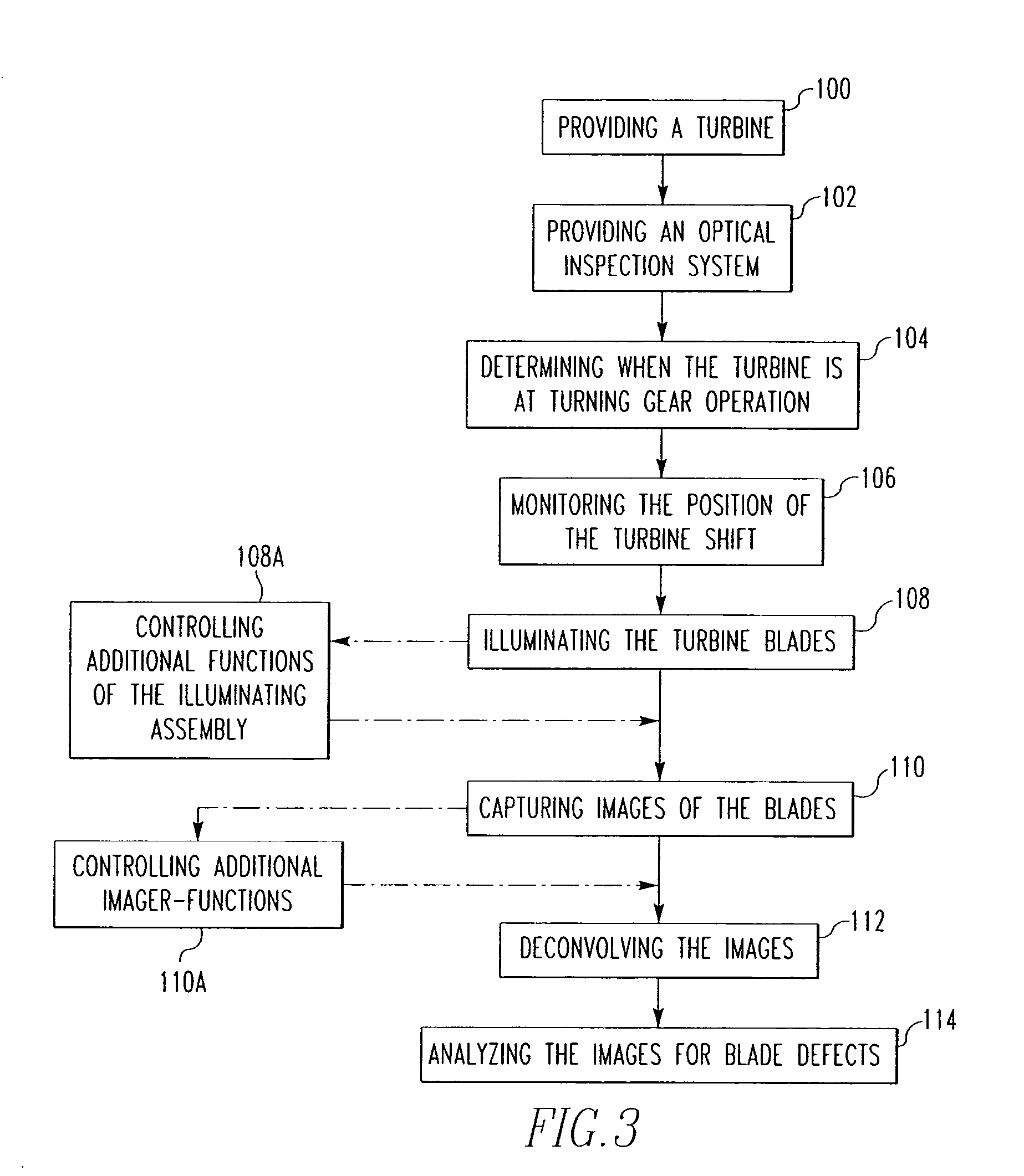
[0025] The invention will be described as applied to optical TBC-monitoring of the blades of a power generation station combustion turbine, although it will become apparent that it could also be applied to inspection of the blades of other types of turbines, such as, for example, gas turbines used in aircraft engines and other gas turbines.

[0026] For purposes of the description hereinafter, the terms “upper,”“lower,”“top,”“bottom,”“left,”“right,” and derivatives thereof shall relate to the invention, as it is oriented in the drawing figures. However, it is to be understood that the invention may assume various alternatives and step sequences, except where expressly specified to the contrary. It is also to be understood that the specific elements and processes illustrated in the drawings and described in the following specification, are simply exemplary embodiments of the invention. Therefore, specific dimensions, orientations and other physical characteristics related to the embodi...


PUM


Abstract

An optical inspection system is for visually inspecting the blades of a turbine at turning gear operation. The inspection system includes an imager for capturing images of the blades, an optical passage coupled to the imager and structured to provide maximum viewing area of the blades through an inspection port in the turbine and an illuminating assembly adapted to illuminate the blades while the imager captures images thereof. A method wherein the captured blade images are inspected for blade defects, is also disclosed.

Description

BACKGROUND OF THE INVENTION [0001] 1. Field of the Invention [0002] The present invention relates generally to inspection of turbine blades and, more particularly, to an optical inspection system for visually inspecting turbine blades during the turning gear operation. The invention also relates to a method of visually inspecting turbine blades at turning gear. [0003] 2. Background Information [0004] Gas and steam turbines for electrical power generation are very expensive (i.e., tens of millions of dollars each). For maximum efficiency, they should not be removed from service for inspection or maintenance unless absolutely necessary. However, defects in the blades of large turbines can cause serious damage and possibly injury. It is, therefore, necessary to be able to promptly detect the formation of blade defects. [0005] Reliable and early detection of failures that could be catastrophic to the power generation unit and the ability to bring the unit through the critical period unt...

Claims


Application Information

Patent Timeline
IPC IPC(8): G06K9/00
CPCF05B2230/80F05B2260/80G01N21/8806G01N21/9515G01N21/954G06T7/0004
Inventor BRUMMEL, HANS-GERD JOHANNLANDI, WILLIAM ALEXANDERLEMIEUX, DENNISTWERDOCHLIB, MICHAELMASTICOLA, STEPHEN PRICE
Owner SIEMENS ENERGY INC
Why Eureka
Try Eureka