Turbine engine shroud segment

Inactive Publication Date: 2006-04-13
GENERAL ELECTRIC CO
View PDF19 Cites 25 Cited by
  • Summary
  • Abstract
  • Description
  • Claims
  • Application Information

AI Technical Summary

Benefits of technology

[0013] According to embodiments of the present invention, to interrupt or cut a potential hoop stress path through the attachment system of integral projection hooks and to reduce hoop stress induced by a radial temperature gradient in the projection hooks of the attachment system, there is provided a plurality of individual, discrete projection hook segments. Such projection hook segments are in at least two axially spaced-apart circumferentially extending rows defini

Problems solved by technology

However as is well known in the art, for example as described in some of the above identified patents, provision of such cooling air is at the expense of engine efficiency.
However, cooling air leakage about edges of a shroud segment can reduce designed efficiency by wasting cooling airflow.
It has been observed that one source of such segment edge leakage can result from shroud segment deformation such as deflection or distortion, generally referred to as “chording”.
As is well known in the gas turbine engine art, other segment distortion or distortion forces can occur, for example in a high pressure turbine.
Other known shroud segment restraints or attachment systems can result in significant hoop stress development in an integral attachment system.
Such metal alloys typically have a CTE in the range of about 7-10 microinch/inch/° F. Therefore, if a CMC type of shroud segment is restrained and cooled on one surface during operation, forces

Method used


Image

  • Turbine engine shroud segment
  • Turbine engine shroud segment
  • Turbine engine shroud segment

Examples


Example

[0019] The present invention will be described in connection with an axial flow gas turbine engine for example of the general type shown and described in the above identified Proctor et al patent. Such an engine comprises, in serial flow communication generally from forward to aft, one or more compressors, a combustion section, and one or more turbine sections disposed axisymmetrically about a longitudinal engine axis. Accordingly, as used herein, phrases using the term “axially”, for example “axially forward” and “axially aft”, refer to relative positions or general directions in respect to the engine axis; phrases using forms of the term “circumferential” refer to circumferential position or direction generally about the engine axis; and phrases using forms of the term “radial”, for example “radially inner” and “radially outer”, refer to relative radial position or direction generally from the engine axis.

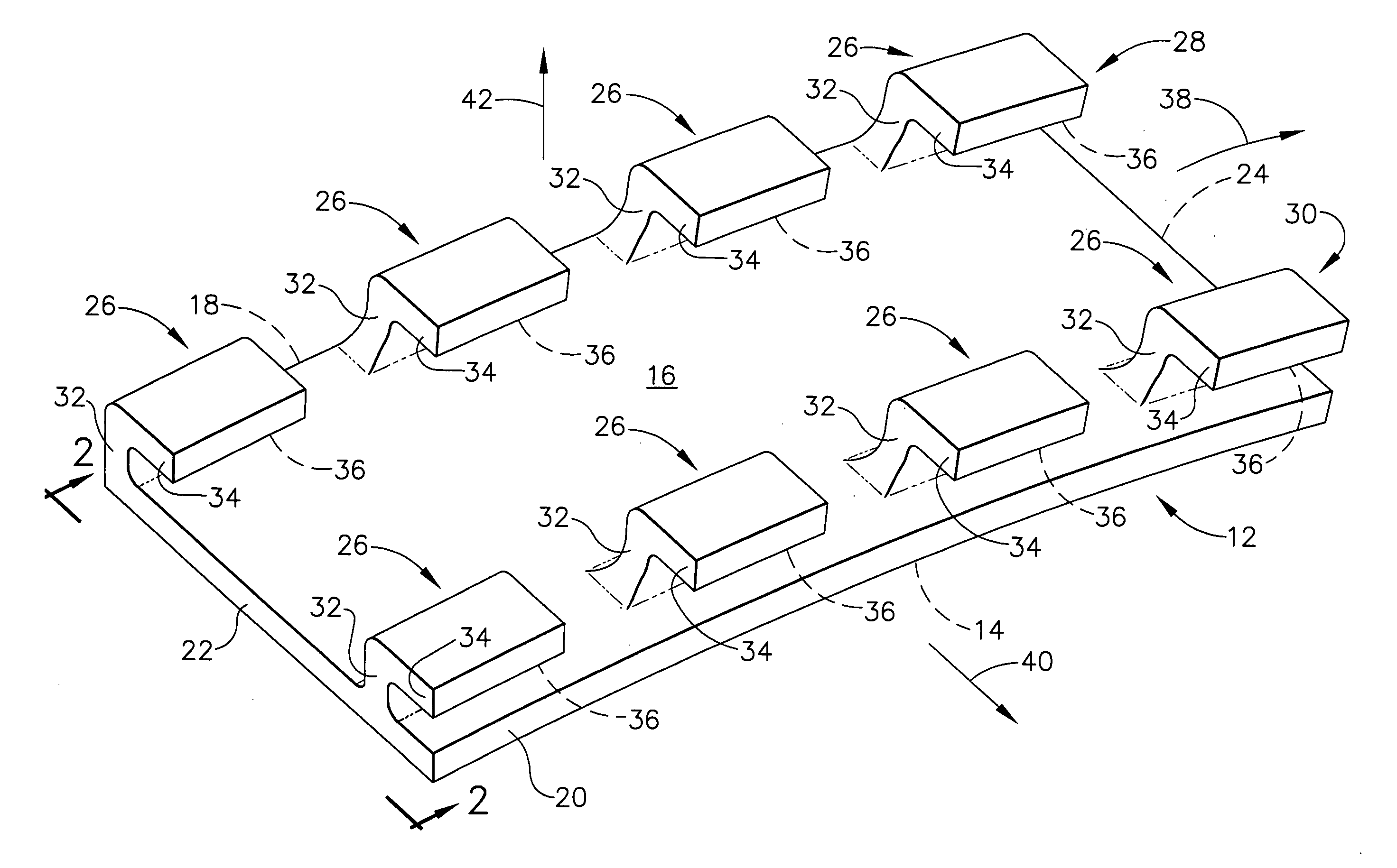
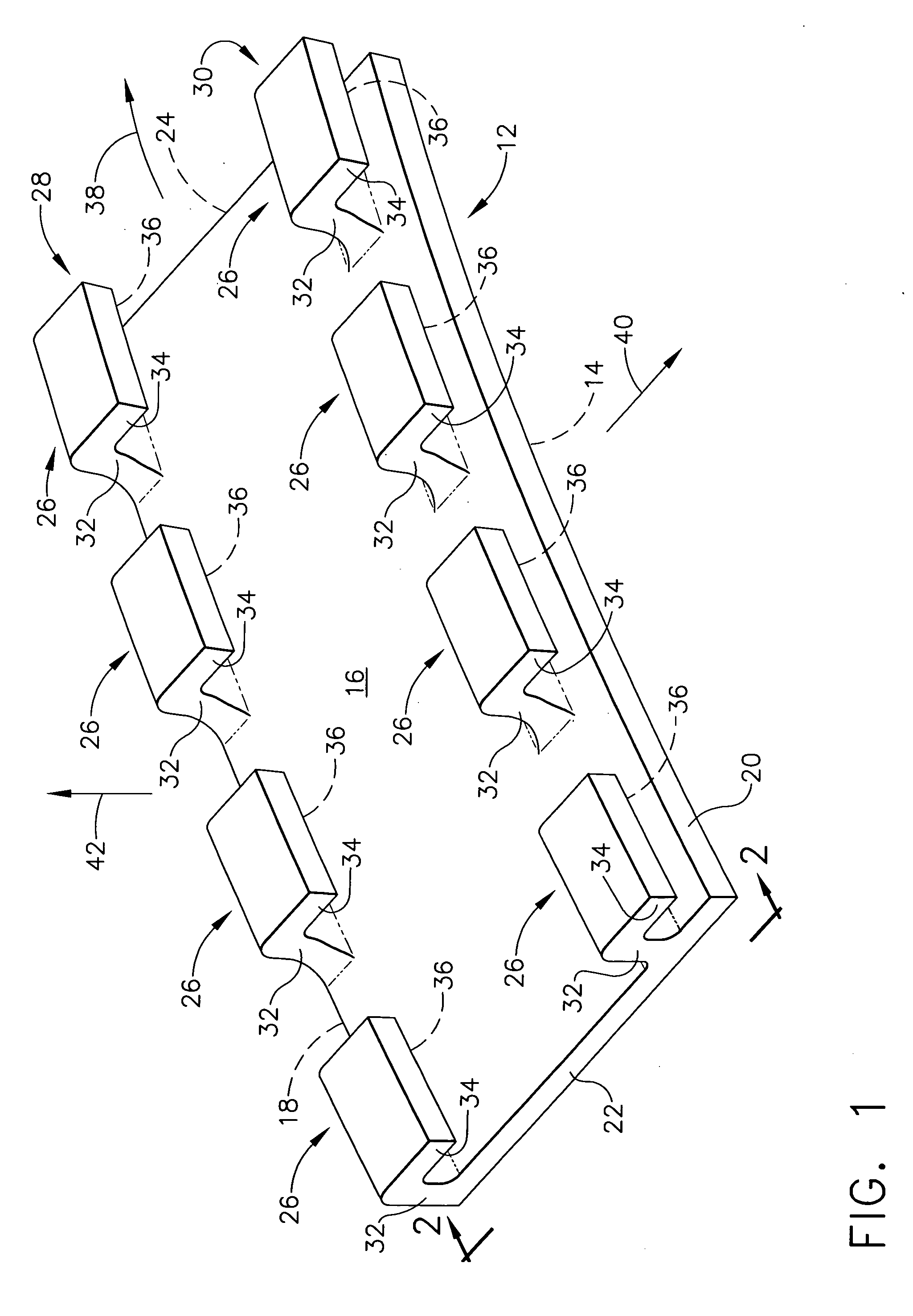
[0020]FIG. 1 is a diagrammatic perspective view of an embodiment of a turbi...


PUM


Abstract

A turbine engine shroud segment comprises a body including an outer surface away from which an integral attachment system projects. The attachment system comprises a plurality of at least two axially spaced apart circumferentially extending rows of discrete projection hook segments to interrupt a potential hoop stress path through the attachment system. Each projection hook segment includes a segment support surface aligned circumferentially and radially with other segment support surfaces in a row.

Description

[0001] The Government has rights in this invention pursuant to Contract No. F33615-97-C-2778-7UW awarded by the Department of Air Force.BACKGROUND OF THE INVENTION [0002] This invention relates generally to turbine engine shroud segments including a surface exposed to elevated temperature engine gas flow. More particularly, it relates to air cooled gas turbine engine shroud segments, for example used in the turbine section of a gas turbine engine, and made of a low ductility material. [0003] A turbine engine shroud segment is a stationary engine component separate and distinct from a component that includes an airfoil, for example a nozzle segment or a stationary blading member. In a gas turbine engine, a plurality of stationary shroud segments is assembled circumferentially about an axial flow engine axis and radially about and spaced apart from rotating blading members, for example about rotating turbine blades. Together, such shroud segments define a part of the radial flowpath b...

Claims


Application Information

Patent Timeline
IPC IPC(8): F01D9/00
CPCF01D9/04F01D25/246
Inventor DARKINS, TOBY GEORGE JR.ALFORD, MARY ELLENNOE, MARK EUGENECRISSMAN, CHRISTOPHER CHARLES
Owner GENERAL ELECTRIC CO
Why Eureka
Try Eureka