

Ultrasonic image boundary extracting method, ultrasonic image boundary extracting apparatus, and ultrasonic imaging apparatus
- Summary
- Abstract
- Description
- Claims
- Application Information
AI Technical Summary
Benefits of technology
Problems solved by technology
Method used
Image

Examples
first embodiment
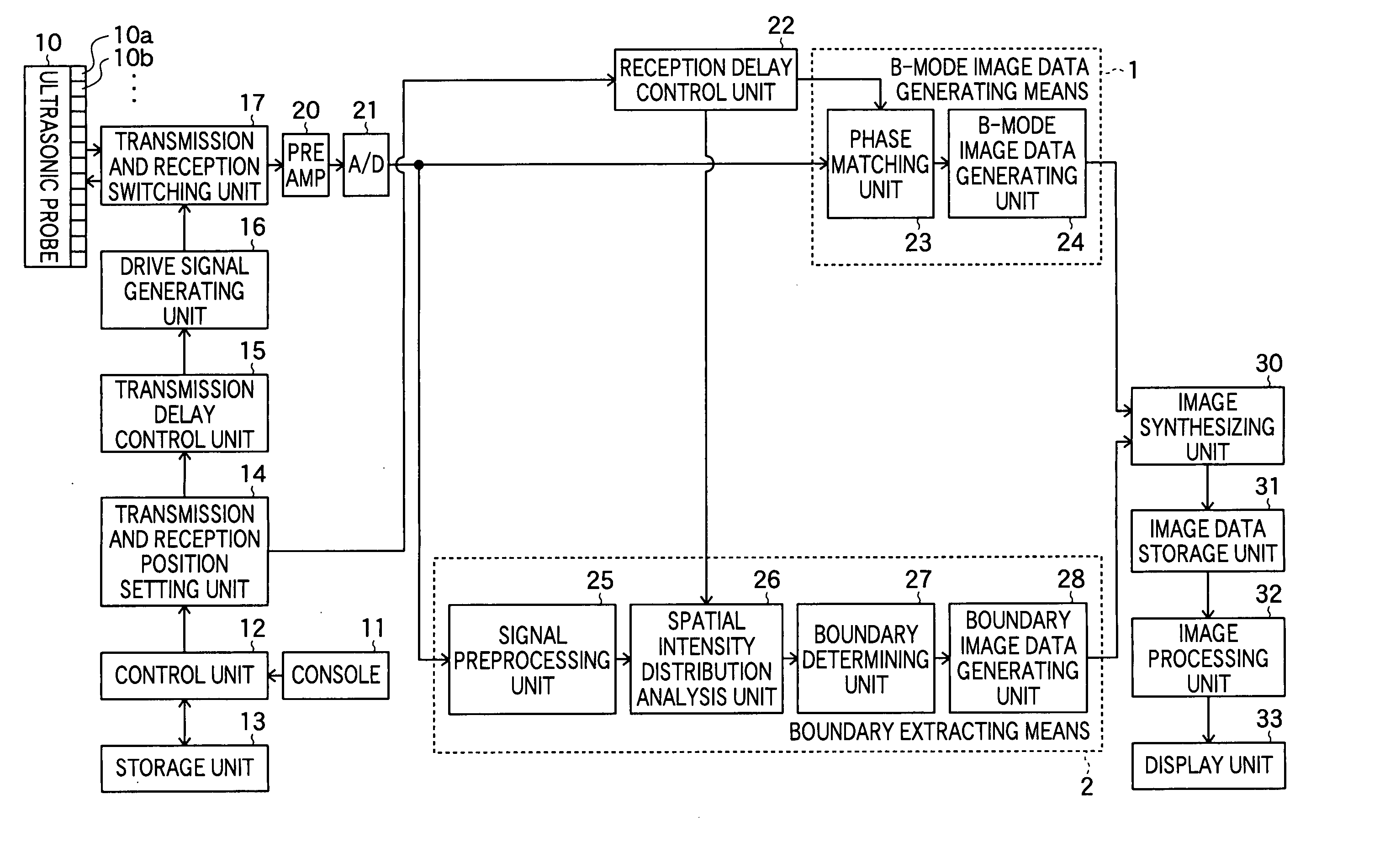
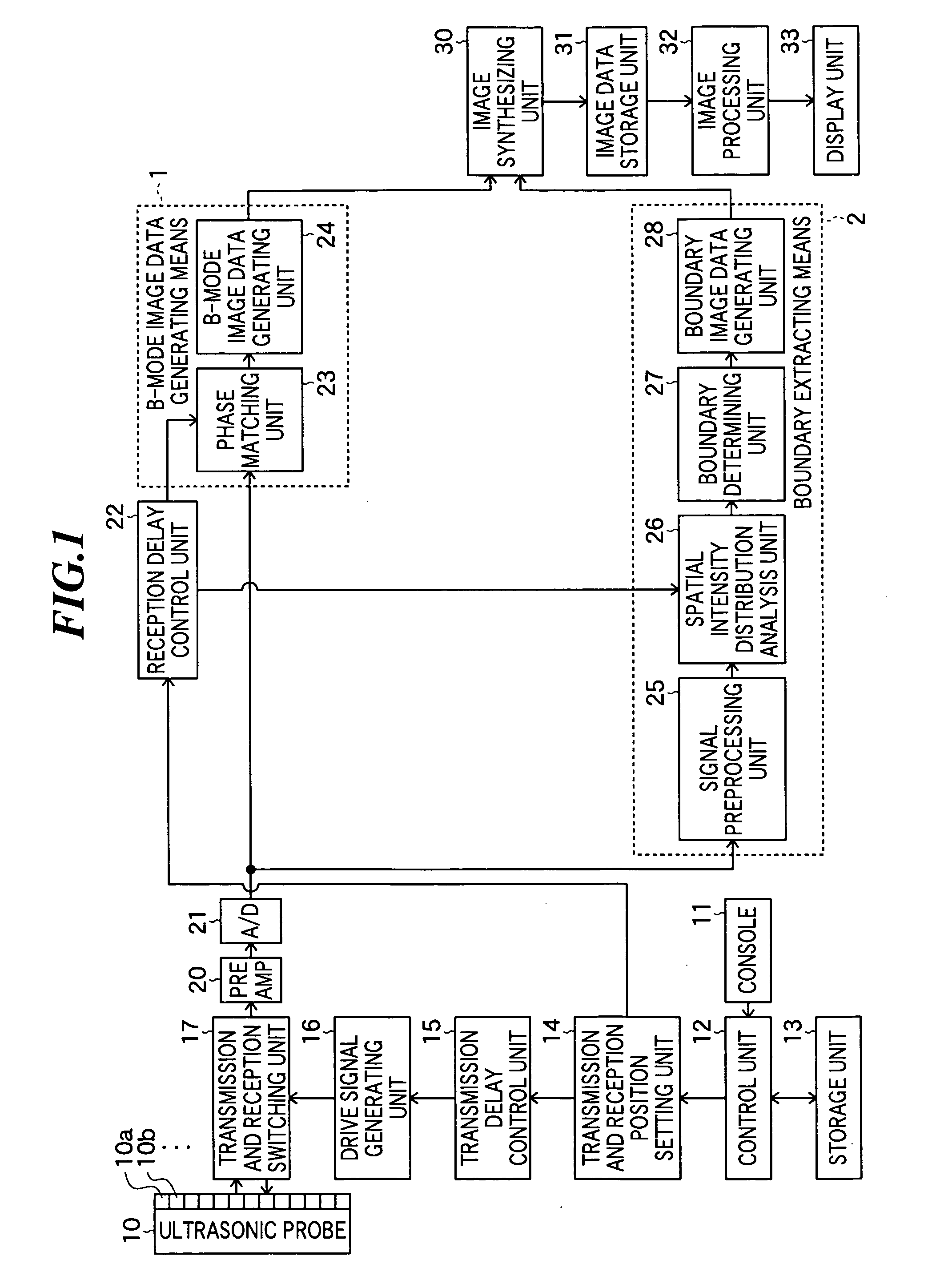
[0049]FIG. 1 is a block diagram showing a constitution of an ultrasonic imaging apparatus according to the present invention. The ultrasonic imaging apparatus according to the embodiment has not only a function of generating B-mode image (B-mode image generating means 1 in FIG. 1) which is owned by a general ultrasonic imaging apparatus, but also a function of extracting boundaries between plural different tissues (boundary extracting means 2 in FIG. 1).
[0050] As shown in FIG. 1, the ultrasonic imaging apparatus according to the present invention includes an ultrasonic probe 10, a console 11, a control unit 12, a storage unit 13, a transmission and reception position setting unit 14, a transmission delay control unit 15, a drive signal generating unit 16, and a transmission and reception switching unit 17.
[0051] The ultrasonic probe 10 is used by being abutted on the object to transmit ultrasonic waves to an object to be inspected and receive ultrasonic waves reflected from the obj...
second embodiment
[0105] Next, an ultrasonic imaging apparatus according to the present invention will be described. FIG. 8 is a block diagram showing a constitution of the ultrasonic imaging apparatus according to the embodiment.
[0106] As shown in FIG. 8, this ultrasonic imaging apparatus has boundary extracting means 3 in place of the boundary extracting means 2 in the ultrasonic imaging apparatus shown in FIG. 1. Other constitution is the same as that of the ultrasonic imaging apparatus shown in FIG. 1.
[0107] The boundary extracting means 3 includes a signal preprocessing unit 25, a histogram analysis unit 40, and a boundary detection unit 41, and a boundary image data generating unit 28.
[0108] The histogram analysis unit 40 generates a histogram based on plural reception signals on the same phase matching line of the plural reception signals that have been intensity corrected by the signal preprocessing unit 25, and thereby, calculates statistics values representing tissue property characterist...
third embodiment
[0128] Next, an ultrasonic imaging apparatus according to the present invention will be described. FIG. 18 is a block diagram showing a constitution of the ultrasonic imaging apparatus according to the embodiment.
[0129] As shown in FIG. 18, the ultrasonic imaging apparatus has boundary extracting means 4 in place of the boundary extracting means 2 shown in FIG. 1. Other constitution is the same as that of the ultrasonic imaging apparatus shown in FIG. 1.
[0130] The boundary extracting means 4 further has a histogram analysis unit 40 and an algorithm selection unit 50 compared to the boundary extracting means 2 shown in FIG. 1, and a boundary detection unit 51 in place of the boundary detection unit 27.
[0131] The algorithm selection unit 50 provides a statistics value to be used for generating surface property image data and an algorithm for surface property image data generation corresponding to the kind of the statistics value from the statistics value (spatial intensity distribut...
PUM
 Abstract
Description
Claims
Application Information