
Adjustable tandem connectors for corrective devices for the spinal column and other bones and joints

a technology of connecting devices and spinal columns, applied in the field of connecting devices for spinal columns and other bones and joints, can solve the problems of limiting the range of motion of spinal columns, spinal pathologies, and high complexity of spinal columns, and achieve the effect of tightening easily

Inactive Publication Date: 2006-04-13
ZIMMER SPINE INC
View PDF61 Cites 158 Cited by
  • Summary
  • Abstract
  • Description
  • Claims
  • Application Information

AI Technical Summary

Benefits of technology

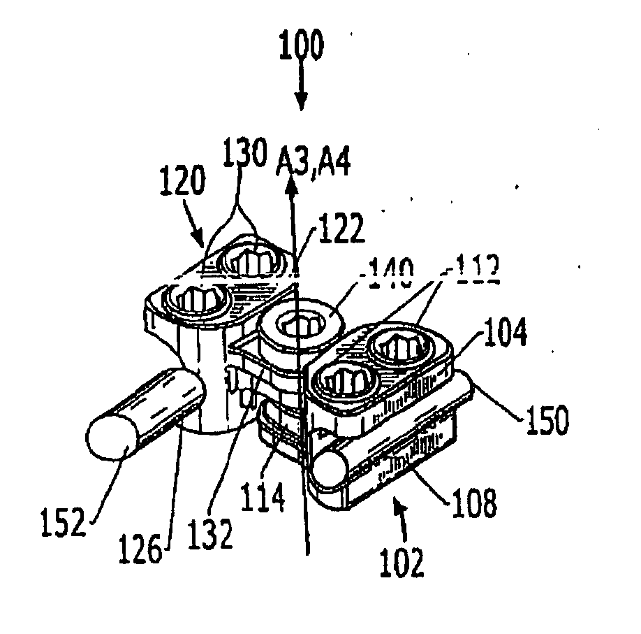
[0010] Connector embodiments of the present invention are configured to address different surgical needs and techniques for interconnecting multiple bone fixation devices (such as rods or plates between vertebrae). As a first aspect, the present invention is directed to a connector that comprises: first and second mating members, each of the members including a body portion, a mating projection and a recess adapted to engage a respective one of at least two bone fixation rods; first and second retaining members; and a fastener. The body portions of the mating members include an aperture having a longitudinal axis that is generally perpendicular to longitudinal axes of the rods, and the mating projections of the first and second mating members include an aperture, the mating projection of the first mating member overlying the mating projection of the second mating member such that their respective apertures are generally axially aligned. The first and second retaining members are inserted into, respectively, the body portion apertures of the first and second mating members to engage a respective rod. The fastener is inserted through the mating projection apertures of the first and second mating members. When the fastener is in a tightened condition, the first and second mating members are prevented from relative rotation, and when the fastener is in a loosened condition, the first and second mating members are free to rotate about an axis of rotation that is generally parallel to the longitudinal axes of the body portion apertures of the first and second mating members. In this configuration, the connector can be manipulated in the coronal plane of the subject to interconnect non-parallel rods, and the rods can be secured and the connector tightened easily by a surgeon from above the spine.
[0011] As a second aspect, a connector of the present invention that can interconnect at least two bone fixation rods comprises: a body portion, a mating projection and a recess adapted to engage a first bone fixation rod; an extension shaft; and a fastener. The mating projection of the body portion has an aperture having a longitudinal axis generally perpendicular to the longitudinal axis of the first rod. The extension shaft has a shank with a slot therein, the shank being inserted into and rotatable relative to the mating portion aperture, and the slot being adapted to receive a second bone fixation rod. The fastener engages the shank of the extension shaft. When the fastener is in a tightened condition, the fastener, shank and mating projection engage the second rod and prevent relative movement thereof, and preferably, when the fastener is in a loosened condition, the second bone fixation rod is free to slide relative to the mating projection parallel to the longitudinal axis of the rod. A retaining member (such as a set screw) can be used to secure the first rod in the recess. This connector embodiment also enables a surgeon to secure bone fixation rods from above the spine.
[0012] As a third aspect, a connector of the present invention for interconnecting bone fixation rods comprises: first and second mating members; first and second retaining components; and a fastener. Each of the first and second mating members includes a body portion, a mating projection and a rod pocket adapted to engage a respective rod. Each of the mating projections of the first and second mating members includes an aperture, and the mating projection of the first mating member overlies the mating projection of the second mating member such that their respective apertures are generally axially aligned. The rod pockets of the first and second mating members having openings positioned above the body portion and facing in a first direction that is generally perpendicular to an axis located between the first and second rod pockets. The first and second retaining components (such as set screws) couple from above with, respectively, the rod pockets of the first and second mating members to secure a bone fixation respective rod. The fastener is inserted through the mating projection apertures of the first and second mating members. This configuration also enables a surgeon to secure bone fixation rods from above while engaging bone fixation rods from below.
[0013] As a fourth aspect, a connector embodiment of the present invention for interconnecting bone fixation rods comprises: a body portion; first and second rod pockets; and first and second retaining components. Each of the rod pockets includes an opening positioned above the body portion and facing in a first direction generally perpendicular to the rod longitudinal axes. The first rod pocket is rotatably attached with one end of the body portion such that the first rod pocket is rotatable relative to the body portion over at least two axes of rotation. The first and second retaining components couple from above with, respectively, the rod pockets of the first and second mating members to secure a respective rod. This connector configuration enables the surgeon to adjust the position and angle of the rod pocket to meet the positional requirements of the rods, and to do so from beneath the rods, while retaining the ability to tighten and secure the rods from above the spine.

Problems solved by technology

In its entirety, the spinal column is highly complex in that it houses and protects critical elements of the nervous system which have innumerable peripheral nerves and arterial and venous bodies in close proximity.
Genetic or developmental irregularities, trauma, chronic stress, tumors, and disease, however, can result in spinal pathologies which either limit this range of motion or threaten the critical elements of the nervous system housed within the spinal column.
In considering the design of a connector, issues include its size (because the connector is implanted in the body near the spine, it should occupy a relatively small volume in order that it be comfortable and non-intrusive for the patent) and its ease of implantation (which can encompass both the ease of attaching an individual rod to the connector and its orientation relative to the patient and the doctor during surgery).

Method used


Image

  • Adjustable tandem connectors for corrective devices for the spinal column and other bones and joints
  • Adjustable tandem connectors for corrective devices for the spinal column and other bones and joints
  • Adjustable tandem connectors for corrective devices for the spinal column and other bones and joints

Examples


Embodiment Construction

[0032] The present invention will now be described more fully hereinafter, in which preferred embodiments of the invention are shown. This invention may, however, be embodied in different forms and should not be construed as limited to the embodiments set forth herein. Rather, these embodiments are provided so that this disclosure will be thorough and complete, and will fully convey the scope of the invention to those skilled in the art. In the drawings, like numbers refer to like elements throughout. Thicknesses and dimensions of some components may be exaggerated for clarity.

[0033] Turning now to the figures, a connector, designated broadly at 100, is illustrated in FIGS. 4 and 5. The connector 100 includes a first mating member 102, a second mating member 120, and a bolt 138. These components are described in detail below.

[0034] The first mating member 102 includes a body portion 104, a finger 108, and a mating projection 114. The body portion 104 is generally wedge-shaped and ...


PUM


Abstract

Connectors for interconnecting rods, fixed to vertebrae and other bones of a subject include a body portion and two recesses or pockets for receiving the rods. These connectors are generally able to be secured to the rods by a tightening a fastener or retaining member from above the spine, which can facilitate the procedure for the surgeon. The connectors can include rotatable or stationary pockets, mating members that pivot and / or translate within the coronal plane of the subject to adjust to the positions of the rods, and extension shafts that pivot to adjust for rod angle.

Description

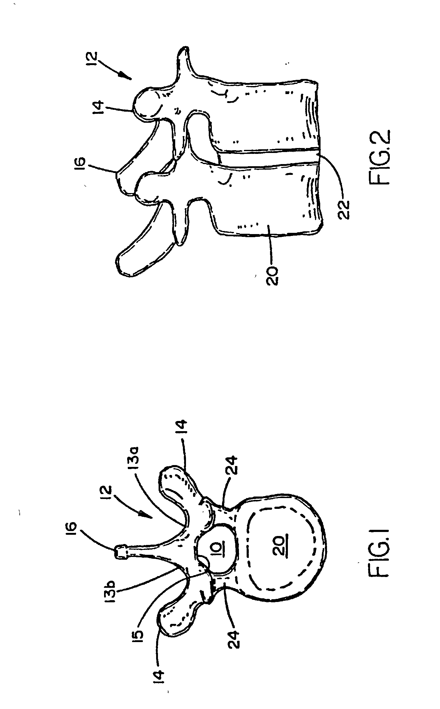
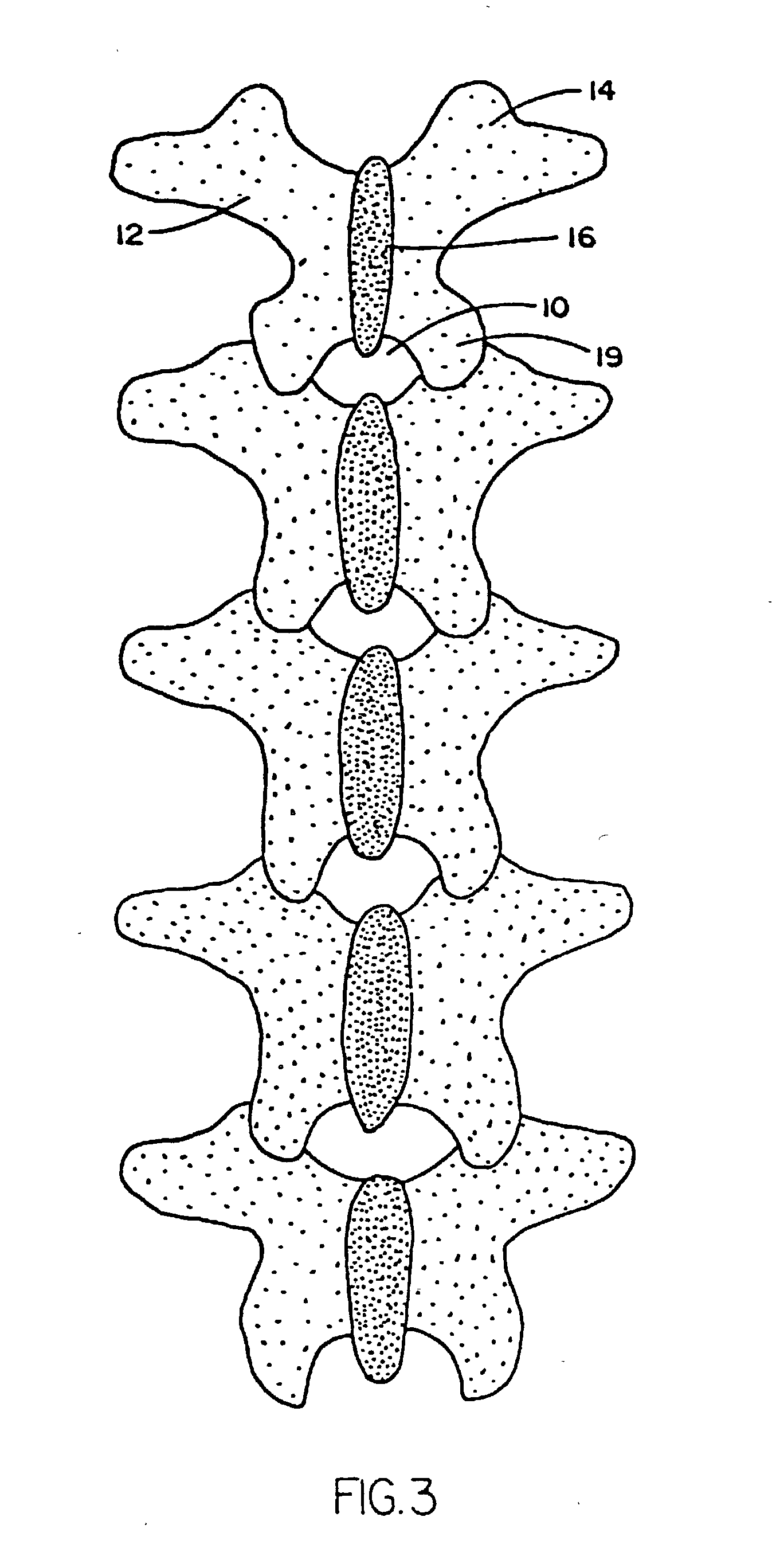
CROSS-REFERENCE TO PROVISIONAL APPLICATION [0001] This application claims the benefit of Provisional Application Ser. No. 60 / 334,771, filed Oct. 31, 2001 entitled Adjustable tandem connectors for corrective devices for the spinal column and other bones and joints, the disclosure of which is hereby incorporated herein by reference in its entirety as if set forth fully herein.FIELD OF THE INVENTION [0002] The present invention relates generally to devices for correcting the spinal column and other bones and joints, and more specifically to connectors for such devices. BACKGROUND OF THE INVENTION [0003] The bones and connective tissue of an adult human spinal column consist of an upper portion (the cervical, thoracic, and lumbar regions) having more than 20 discrete bones, and a lower portion which consists of the sacral bone and the coccygeal bodies. The bones of the upper portion are generally similar in shape, the size of the bones progressively varying from small to large downwardl...

Claims


Application Information

Patent Timeline
Patent Type & Authority Applications(United States)
IPC IPC(8): A61F2/30A61B17/58A61B17/64A61B17/70
CPCA61B17/645A61B17/7044A61B17/705
Inventor ROYCHOWDHURY, SURANJANNGUYEN, DUYCOTA, JEFFREY
Owner ZIMMER SPINE INC
Learn More