Temporary anastomotic seal and method

Inactive Publication Date: 2006-04-13
MAQUET CARDIOVASCULAR LLC
View PDF99 Cites 53 Cited by
  • Summary
  • Abstract
  • Description
  • Claims
  • Application Information

AI Technical Summary

Problems solved by technology

However, performing an aortotomy and a proximal anastomosis on the aorta that is perfused with blood under pressure contribute to substantial losses of blood in the absence of temporary measures taken to curtail blood flow through the aortic hole.
Side-bite and surface-oriented clamping mechanisms have been used to diminish loss of blood during the surgical procedures of punching the aortic hole and anastomosing the graft vessel, but such temporary occlu

Method used


Image

  • Temporary anastomotic seal and method
  • Temporary anastomotic seal and method
  • Temporary anastomotic seal and method

Examples


Embodiment Construction

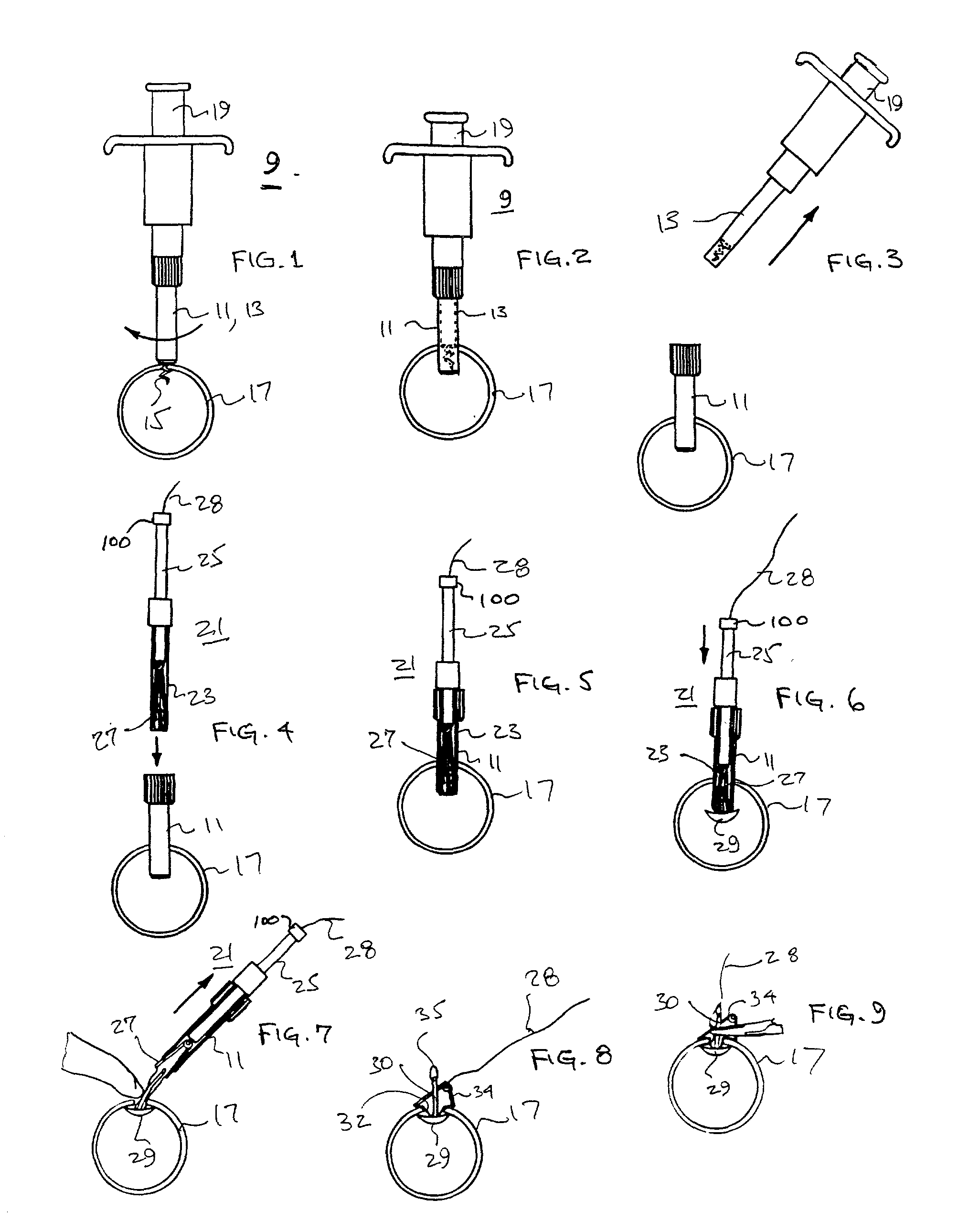
[0040] Referring now to FIGS. 1, 2 and 3, there are shown pictorial views of the aortic punch 9 configured for penetrating the aorta 17 of a patient in preparation for a proximal anastomosis of a bypass vessel to the aorta of the patient. Specifically, an outer hemostatic sheath 111 is coaxially disposed over the lower elongated segment 13 of the aortic punch which supports a corkscrew-type auger 15, as shown in FIGS. 14 and 15. The punch and auger 15 are rotated into a wall of the aorta 17 and the plunger 19 can then be depressed to penetrate the sharpened edge of the lower elongated segment 13 through the aorta wall. The punched-out segment of aorta wall remains captivated on the cork screw 15, and the hemostatic sheath 11 is positioned within the punched hole through the aorta wall. The plunger mechanism 19 and attached elongated lower segment is removed from the hemostatic sheath 11 that remains in position through the aorta wall, as shown in FIG. 3. A fluid-tight seal is includ...


PUM


Abstract

Forming a proximal anastomosis on an aortic wall includes method and instrumentation and apparatus for forming an aortic puncture and inserting into the vessel through the puncture a fluid-impervious sealing element with a protruding retainer. An anastomosis of a graft vessel over the puncture is partially completed with the retainer of the sealing element protruding through the partial anastomosis. The retainer facilitates removal of the sealing element from the partial anastomosis prior to completion of the procedure.

Description

RELATED APPLICATION [0001] This application is a continuation-in-part of application Ser. No. 10 / 033,614, entitled “Temporary Seal And Method For Facilitating Anastomosis,” filed on Dec. 26, 2001 by A. Chin et al.FIELD OF THE INVENTION [0002] This invention relates to coronary bypass grafting surgery and more particularly to instruments and method to facilitate performing an aortotomy and proximal anastomosis, for example, associated with coronary artery bypass grafting surgery. BACKGROUND OF THE INVENTION [0003] Contemporary coronary artery bypass grafting surgery is performed on a beating heart to obviate complications commonly associated with prior surgical practices of transitioning a patient onto and off of a heart-lung machine that maintained circulation while the heart was in quiescent condition during construction of a coronary arterial bypass. However, performing an aortotomy and a proximal anastomosis on the aorta that is perfused with blood under pressure contribute to su...

Claims


Application Information

Patent Timeline
IPC IPC(8): A61B17/08A61B17/00A61B17/11A61B17/32
CPCA61B17/0057A61B17/32053A61B2017/00362A61B2017/00637A61B2017/00659A61B2017/1107A61B17/12022A61B17/12027A61B17/12031A61B17/12036A61B17/1204A61B17/12045A61B2017/00575A61B2017/0061A61B2017/00632A61B2017/00641
Inventor CHIN, ALBERT K.MOREJOHN, DWIGHTTAYLOR, CHARLES S.CHOI, STEVEN B.REIS, EUGENEDAVIS, JOHN W.WILLIS, GEOFFREY H.PINEDA, EDWARD A.VEPA, KUSHAL P.
Owner MAQUET CARDIOVASCULAR LLC
Why Eureka
Try Eureka