Linear drive with emergency adjustment possibility

Inactive Publication Date: 2006-04-20
AB SKF
View PDF6 Cites 21 Cited by
  • Summary
  • Abstract
  • Description
  • Claims
  • Application Information

AI Technical Summary

Benefits of technology

[0010] In a solution that is especially favorable in terms of design, a loop spring, which is known per se and which is also called coil spring or brake spring, may be provided. Such a machine element is especially suitable in connection with the present invention because such a coil spring is already frequently used in such linear drives anyway, especially in connection with emergency adjusting means for linear drives. Even though such machine elements are sufficiently known in connection with linear drives of this type, the function according to the present invention has not yet been embodied so far. The preferred embodiment of a linear drive with a coil spring makes it possible to expand existing constructions with the function according to the present invention with an especially low effort.

Problems solved by technology

These measures may preferably be taken in the adjusting device itself For example, by limiting the possibilities of actuation, the adjusting means can either be actuated for this purpose in one direction only or, in case of actuation in, e.g., two directions, only one direction of actuation can also lead to uncoupling of the driven side from the drive or the motor.

Method used


Image

  • Linear drive with emergency adjustment possibility
  • Linear drive with emergency adjustment possibility
  • Linear drive with emergency adjustment possibility

Examples


Embodiment Construction

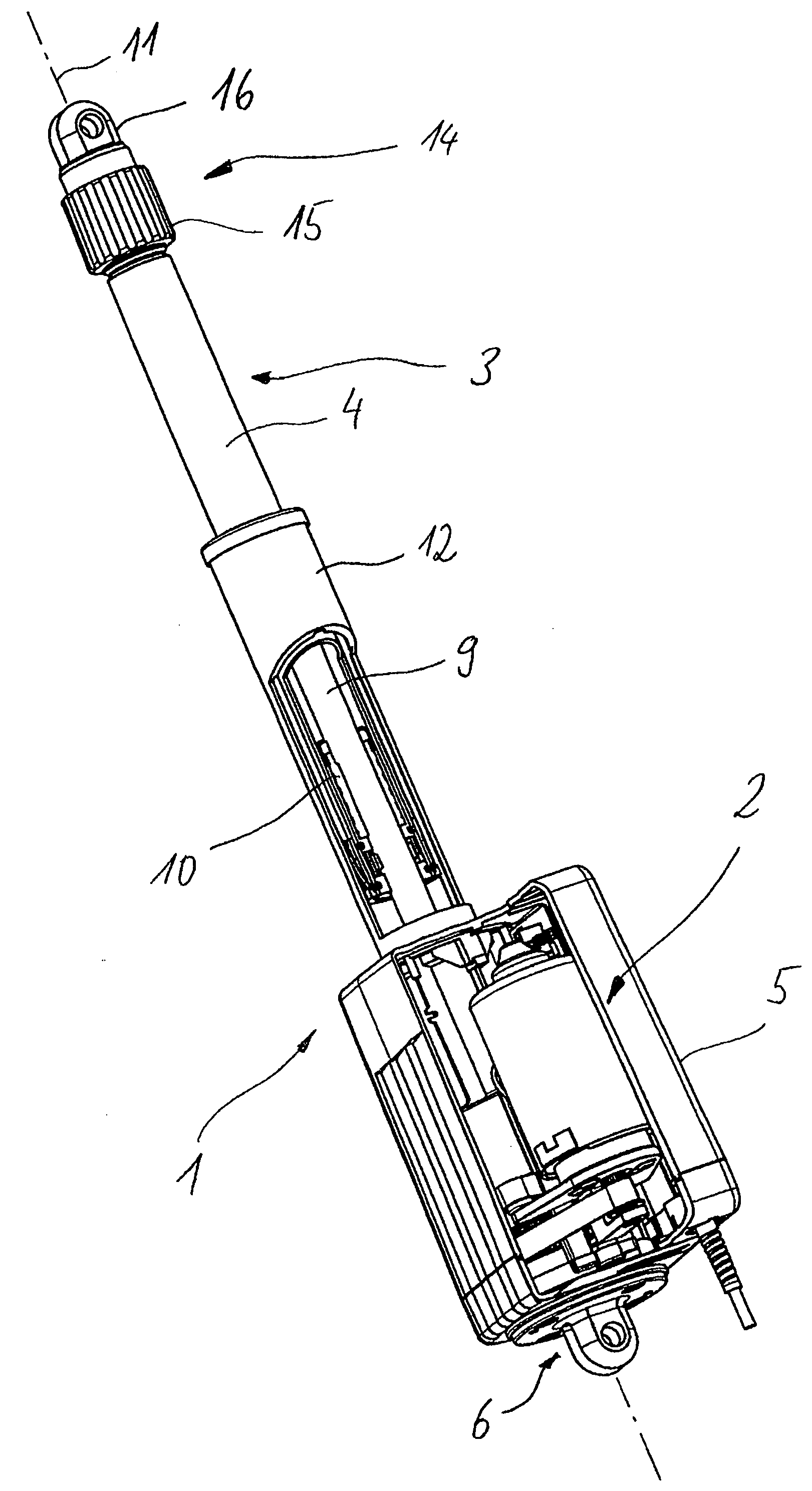
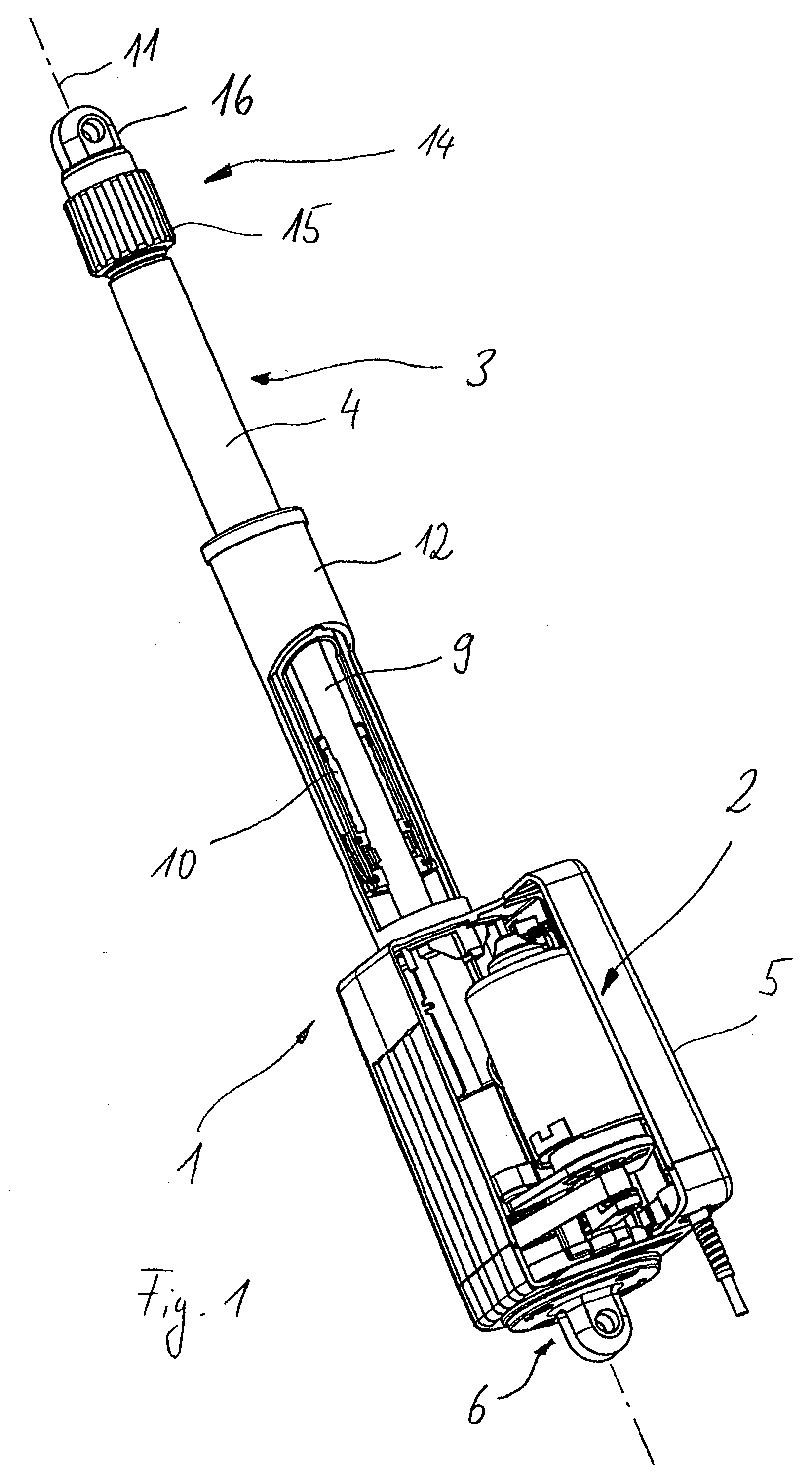
[0027] Referring to the drawings in particular, the linear drive shown in FIG. 1 has on a drive side 1 an electric motor 2, by the rotary drive motion of which a longitudinal motion of a push rod 4 provided on a drive side 1 is brought about. A drive-side fork head 6, with which the linear drive can be fastened in a plant, a medical inventory item, a piece of furniture, a machine or the like, is provided at a housing 5 of the motor 2. The principal applications of this linear drive are patient beds, operating tables, lifters, especially patient lifters, and other like medical and related applications.

[0028] A rotary motion of a motor shaft is transmitted to a spindle 9, which may have a non-self-locking or a self-locking external thread. To transform the rotary motion of the motor into a slow motion, a gear mechanism, especially a toothed gearing, for example, a planet gear, may be inserted between the motor 2 and the spindle 9.

[0029] A threaded nut 10 is located on the spindle 9....


PUM


Abstract

The possibility of manipulating errors of an emergency or quick adjusting means shall be ruled out at least extensively in a linear drive. It is proposed for this purpose, for a linear drive with a spindle (9), which can be rotatingly driven on the drive side by a motor (2), where the rotary motion of said spindle in the direction of the driven side (3) of the linear drive can be converted into an at least essentially translatory motion of a gear member, which is in functional connection with the spindle (9), and said linear drive is provided, furthermore, with a torsional connection between the gear member and a connection part. The linear drive can be connected with the connection part on a driven side (3) to a load, which is to be adjusted, the torsional connection being able to be released by an adjusting device in order to permit a motor-independent adjusting motion of the linear drive, even though structure for emergency and / or quick adjustment are present. The torsional connection is able to be released by an adjusting element of the adjusting device only for motions in always only a single, predetermined relative direction of rotation between the spindle and the gear member.

Description

CROSS REFERENCE TO RELATED APPLICATIONS [0001] This application claims the benefit of priority under 35 U. S.C. §119 of Swiss Application CH 01543 / 04 filed Sept. 20, 2004, the entire contents of which are incorporated herein by reference. FIELD OF THE INVENTION [0002] The present invention pertains to a linear drive with a spindle, which can be rotatingly driven on the drive side by a motor and whose rotary motion can be converted in the direction of the driven side of the linear drive into an at least essentially translatory motion of a gear member functionally connected to the spindle, the linear drive having, furthermore, a torsional connection between the gear member and a connection part, wherein the linear drive can be connected on a driven side to a load, which is to be adjusted and, and the torsional connection being able to be released by means of an (emergency or quick) adjusting means in order to permit a motor-independent adjusting motion of the linear drive. It is assum...

Claims


Application Information

Patent Timeline
IPC IPC(8): F16H27/02F16H25/24
CPCF16H25/2454F16H2025/2071Y10T74/18576F16H2025/2463F16H2025/2081
Inventor JAECKLIN, VICTORSOLTERMANN, MARCEL
Owner AB SKF
Why Eureka
Try Eureka