Flow regulating valve

a flow regulating valve and flow control technology, applied in the field of valves, can solve the problems of pressure drop across the valve, flow is limited, and the flow rate cannot be positively controlled, so as to reduce power loss and heat, enhance the flow of fluid, and minimize the restriction

Active Publication Date: 2006-04-20
TERRA DRIVE SYST
View PDF16 Cites 2 Cited by
  • Summary
  • Abstract
  • Description
  • Claims
  • Application Information

AI Technical Summary

Benefits of technology

[0016] An advantage of the present invention is that it minimizes the restriction and enhances the return flow of fluid through the valve and thereby reduces power losses and the heat generated by the flow of return fluid through the valve in the unregulated direction. Additionally, by removing the spring from the interior of the piston, the calibration orifice of the piston may be enlarged thereby reducing the pressure drop experienced by fluid flowing through the calibration orifice and enhancing the operation of the valve for fluid flow in both the regulated and unregulated flow directions. The regulation of the fluid flow through the valve assembly in the regulated flow direction is also relatively smooth without abrupt transitions as the flow rate changes.

Problems solved by technology

Consequently, valve 10 does not positively control the flow rate of the hydraulic fluid through the valve in the return direction and flow is limited by the size of the metering orifice 30.
In other words, the valve does not regulate the flow of fluid through the valve when the fluid is flowing in the direction indicated by arrows 27 in FIG. 2 but rather the limited size of metering orifice 30 restricts the flow of fluid through the valve resulting in a pressure drop across the valve and undesirable power losses and heating of the fluid.
While this may be acceptable for the operation of a hydraulic lift, such a transition could result in the rough and unacceptable operation of a hydraulic motor driven wheel.

Method used


Image

  • Flow regulating valve
  • Flow regulating valve
  • Flow regulating valve

Examples


Embodiment Construction

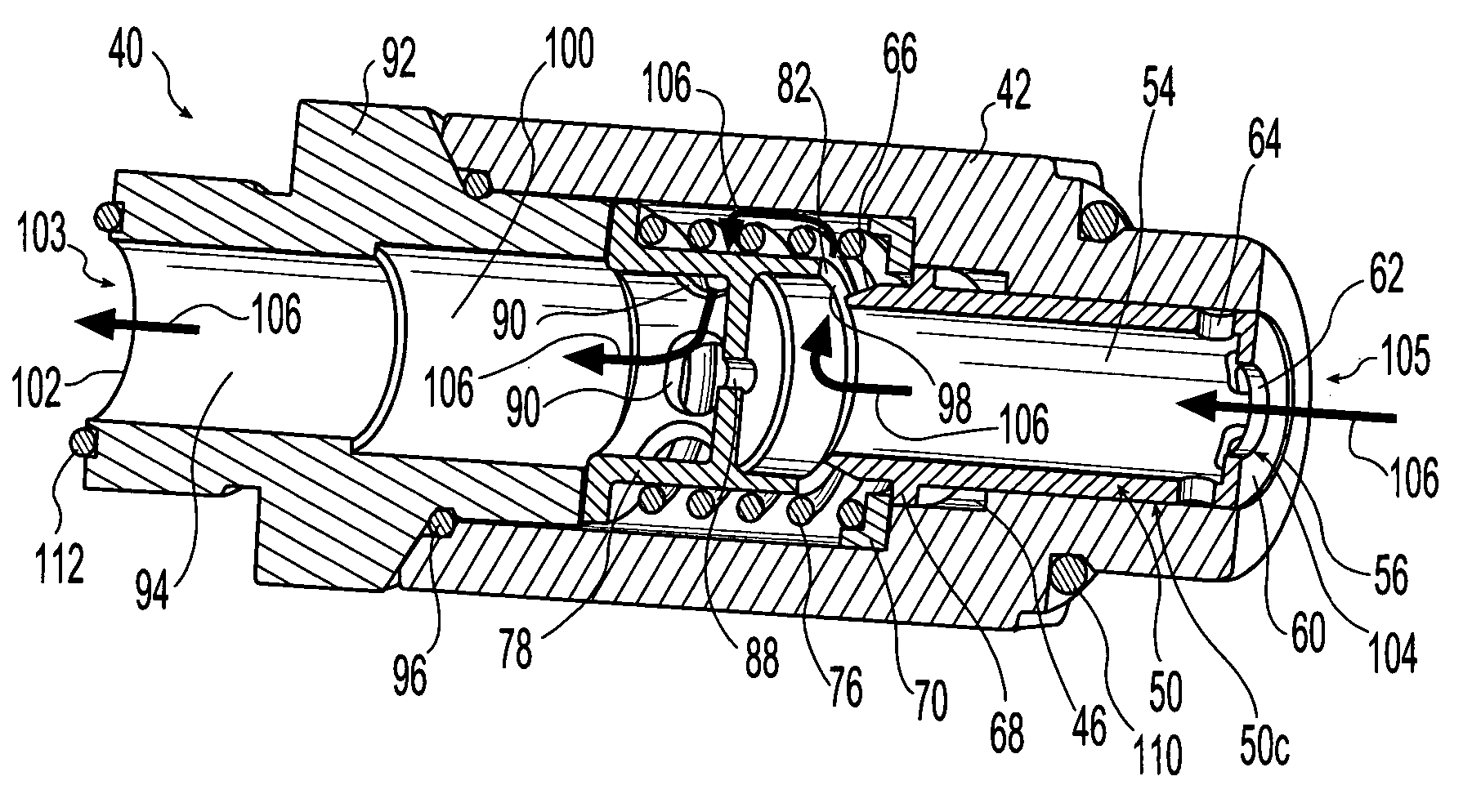
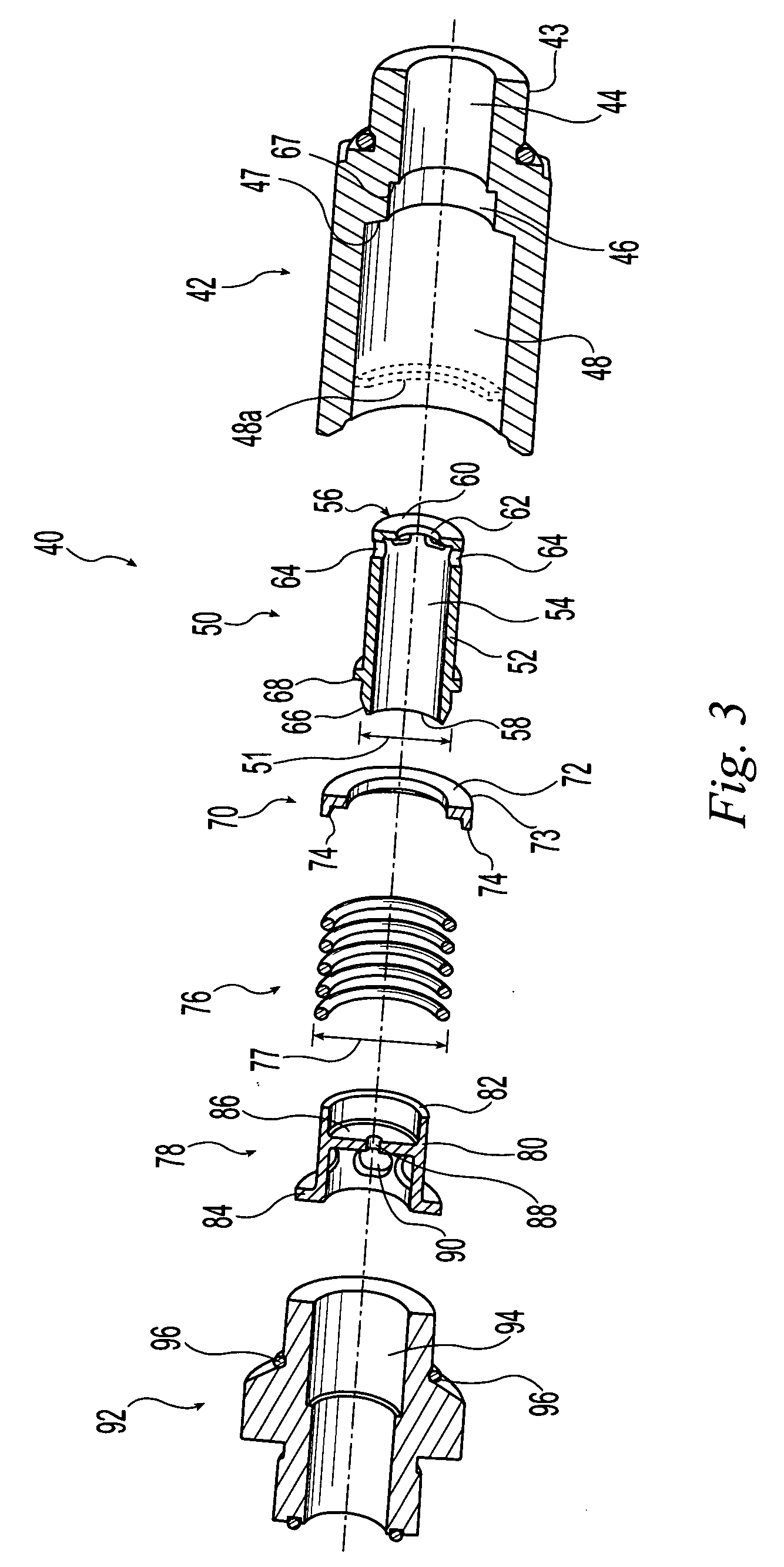
[0025] A valve assembly 40 in accordance with the present invention is shown in an exploded view in FIG. 3. Valve assembly 40 includes a valve body 42 having a passageway defined by three axially aligned cylindrical bore sections 44, 46, 48 of differing diameters. In the illustrated embodiment, valve member 50 takes the form of a piston 50 reciprocatingly disposed in valve body 42. Piston 50 includes a cylindrical sidewall 52 that defines interior passage 54 extending from first axial end 56 of piston 50 to the opposite second axial end 58 of piston 50. An endwall 60 is located at first axial end 56 and includes a metering orifice 62. A plurality of circumferentially spaced openings 64 are located in sidewall 52 proximate first axial end 56. Second axial end 58 of piston 50 is open, i.e., it does not include an endwall or otherwise define a restriction within axial passage 54. The radially outer surface of sidewall 52 at second axial end 58 forms a tapered surface 66 which cooperate...


PUM


Abstract

A valve assembly that includes a valve body defining a fluid passage. First and second ends of the fluid passage define first and second ports for fluid flow. A spring and piston are located in the fluid passage. The piston has a travel length extending between first and second positions with a third position located therebetween. The spring biases the piston from the first toward the third position and is located outside the axial piston passage. The piston at least partially defines a first, second and at least one third opening. The first opening defines a variable constriction which increases in size as the piston moves from the first to third positions. The piston end wall defines the second opening and the piston sidewall defines the third openings. Movement of the piston from the third to second position exposes the third openings increasing the area of the second port.

Description

BACKGROUND OF THE INVENTION [0001] 1. Field of the Invention [0002] The present invention relates to valves and, more specifically, to a flow regulating valve that regulates the flow of fluid in one direction and allows the generally unregulated flow of fluid in the opposite direction. [0003] 2. Description of the Related Art [0004] In vehicles employing hydraulic systems, it is known to employ valves that limit the flow of the hydraulic fluid through a fluid line leading to a hydraulic actuator such as a hydraulic motor or cylinder to a maximum flow rate. For example, in a combine harvester it is known to use an internal combustion engine to power a hydraulic pump. The hydraulic pump provides hydraulic fluid under pressure to a hydraulic circuit. Each of the driven wheels of the combine harvester may include a separate hydraulic motor that is powered by the hydraulic circuit. Each of the motors may be located in a separate loop in communication with the hydraulic circuit. By revers...

Claims


Application Information

Patent Timeline
Patent Type & Authority Applications(United States)
IPC IPC(8): G05D7/01
CPCF16K17/26G05D7/0133Y10T137/7792Y10T137/7839Y10T137/87539
Inventor KIRBY, LANE C.
Owner TERRA DRIVE SYST
Why Eureka
Try Eureka