Core spray sparger T-box clamp apparatus and method for installing the same

a technology of clamping apparatus and sparger, which is applied in the field of nuclear reactors, can solve problems such as system damage and unpredictability of leakag

Inactive Publication Date: 2006-04-20
GENERAL ELECTRIC CO
View PDF16 Cites 26 Cited by
  • Summary
  • Abstract
  • Description
  • Claims
  • Application Information

AI Technical Summary

Problems solved by technology

These three welded joints are susceptible to cracking, and in the event that through-wall circumferential cracking should occur at these welded joints, un

Method used


Image

  • Core spray sparger T-box clamp apparatus and method for installing the same
  • Core spray sparger T-box clamp apparatus and method for installing the same
  • Core spray sparger T-box clamp apparatus and method for installing the same

Examples


Embodiment Construction

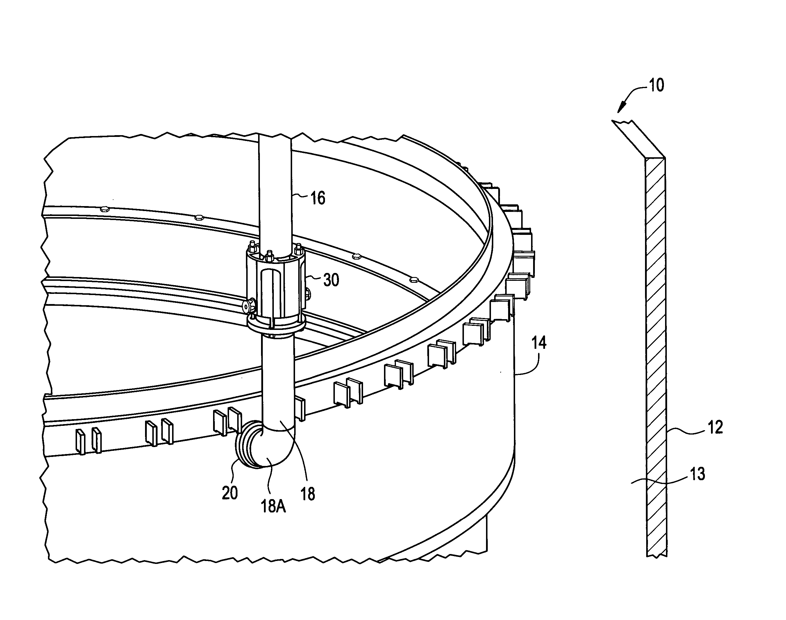
[0036] A core spray sparger T-box attachment assembly in accordance with the invention is designed to mechanically clamp the replacement core spray downcomer piping (lower sectional replacement) to the shroud, and structurally replace welds that attach the cover plate and sparger pipe to the sparger T-box.

[0037]FIG. 1 is an isometric, partial cross-sectional view, with parts cut away, of a reactor pressure vessel (RPV) of a boiling water nuclear reactor. In particular, FIG. 1 illustrates a shroud showing the spatial arrangement of a downcomer piping and lower sectional replacement which encompasses a coupling and replacement piping elbow. A reactor pressure vessel (RPV) 10 includes a vessel wall 12 and a shroud 14 which surrounds the reactor core (not shown) of RPV 10. An annulus 13 may be formed between vessel wall 12 and shroud 14. The space inside the annulus may be limited, as most reactor support piping may be located within the annulus.

[0038] In the event of a reactor plant ...


PUM


Abstract

A core spray sparger T-box attachment assembly for a nuclear reactor pressure vessel, wherein the pressure vessel includes a shroud, a sparger T-box penetrating the shroud, a plurality of sparger distribution header pipes coupled to the sparger T-box, and a downcomer pipe. The sparger header pipes may include at least one sparger nozzle, and the sparger T-box attachment assembly may include a downcomer pipe coupling and a sparger T-box clamp. The sparger T-box clamp may include an anchor plate having a draw bolt opening to receive a draw bolt, a first clamp block substantially aligned at one end of the anchor plate, and a second clamp block substantially aligned at the other end of the anchor plate.

Description

BACKGROUND OF INVENTION [0001] 1. Field of the Invention [0002] This invention relates generally to nuclear reactors and more particularly, to assemblies and methods for repairing piping within reactor pressure vessel of such reactor. [0003] 2. Description of Related Art [0004] A reactor pressure vessel (RPV) of a boiling water reactor (BWR) typically has a generally cylindrical shape and is closed at both ends, e.g., by a bottom head and a removable top head. A core shroud, or shroud, typically surrounds the core and is supported by a shroud support structure. [0005] Boiling water reactors have numerous piping systems, and such piping systems are utilized, for example, to transport water throughout the RPV. For example, core spray piping is used to deliver water from outside the RPV to core spray spargers inside the RPV. The core spray piping and spargers deliver water flow to the reactor core. [0006] Intergranular stress corrosion cracking (IGSCC) is a known phenomenon occurring i...

Claims


Application Information

Patent Timeline
IPC IPC(8): F16L5/00
CPCG21C13/02G21C17/017G21Y2002/303G21Y2002/40G21Y2004/301G21Y2004/504Y02E30/40Y02E30/30G21C13/036G21C15/18
Inventor JENSEN, GRANT C.
Owner GENERAL ELECTRIC CO
Why Eureka
Try Eureka