Electromechanical strut

a technology of electromechanical and strut, which is applied in the direction of roofs, doors, wing accessories, etc., can solve the problems of counterbalance to weight, and achieve the effect of storing potential energy and reducing the diameter of the housing

Active Publication Date: 2006-04-20
MAGNA CLOSURES INC
View PDF9 Cites 72 Cited by
  • Summary
  • Abstract
  • Description
  • Claims
  • Application Information

AI Technical Summary

Benefits of technology

[0008] The present invention provides an electromechanical strut using an inline motor coupled to an inline planetary gear that are both mounted in the housing. The motor-gear assembly drives a power screw and nut assembly in the upper housing, extending or retracting an extensible shaft. Additionally, a power spring mounted coaxially around the power screw urges the extensible shaft to the extended position and provides a mechanical counterbalance to the weight of a lift gate on the shaft. As the shaft extends, the power spring uncoils, assisting the motor-gear assembly in raising the lift gate. Retracting the shaft recoils the spring, storing potential energy. Thus, a lower torque motor-gear assembly can be used, reducing the diameter of the housing.

Problems solved by technology

Additionally, a power spring mounted coaxially around the power screw urges the extensible shaft to the extended position and provides a mechanical counterbalance to the weight of a lift gate on the shaft.

Method used


Image

  • Electromechanical strut
  • Electromechanical strut
  • Electromechanical strut

Examples


Embodiment Construction

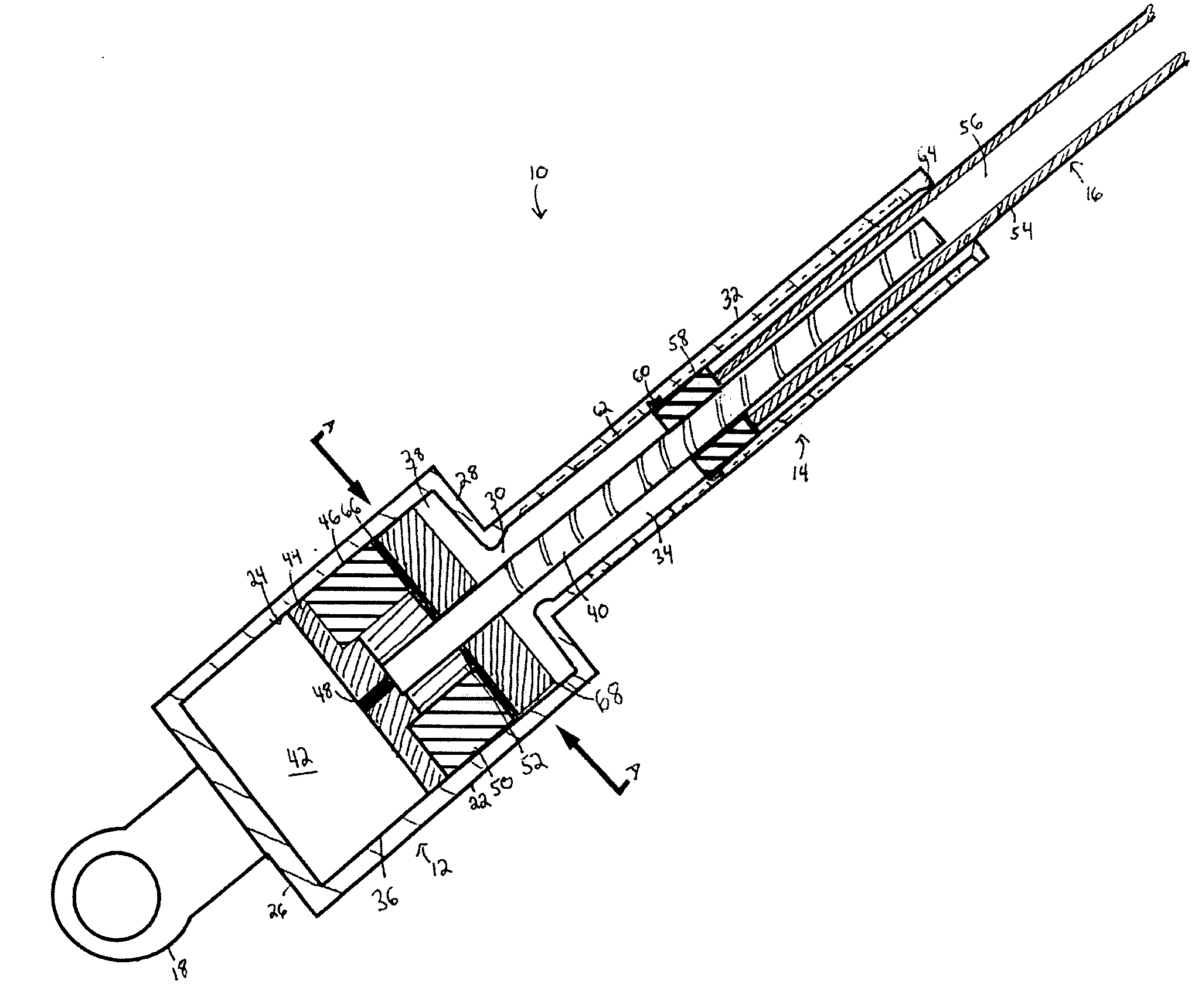
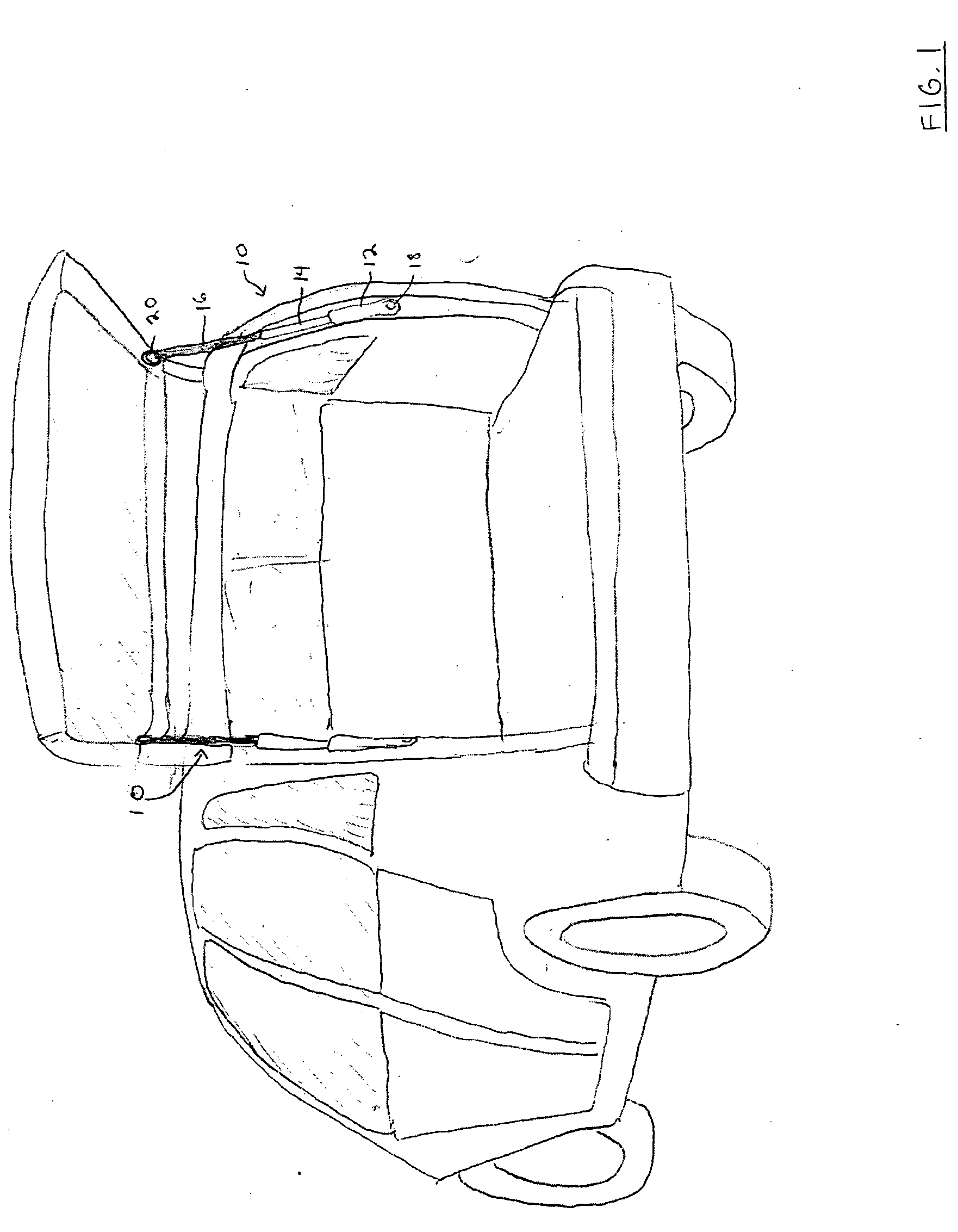
[0013] Referring now to FIGS. 1 and 2, an embodiment of the invention mounted to a motor vehicle is shown generally at 10. Electromechanical strut 10 includes a lower housing 12, an upper housing 14, and an extensible shaft 16. A pivot mount 18, located at an end of lower housing 18 is pivotally mounted to a portion of the vehicle body that defines an interior cargo area in the vehicle. A second pivot mount 20 is attached to the distal end of extensible shaft 16, relative to upper housing 18, and is pivotally mounted to the lift gate of the vehicle.

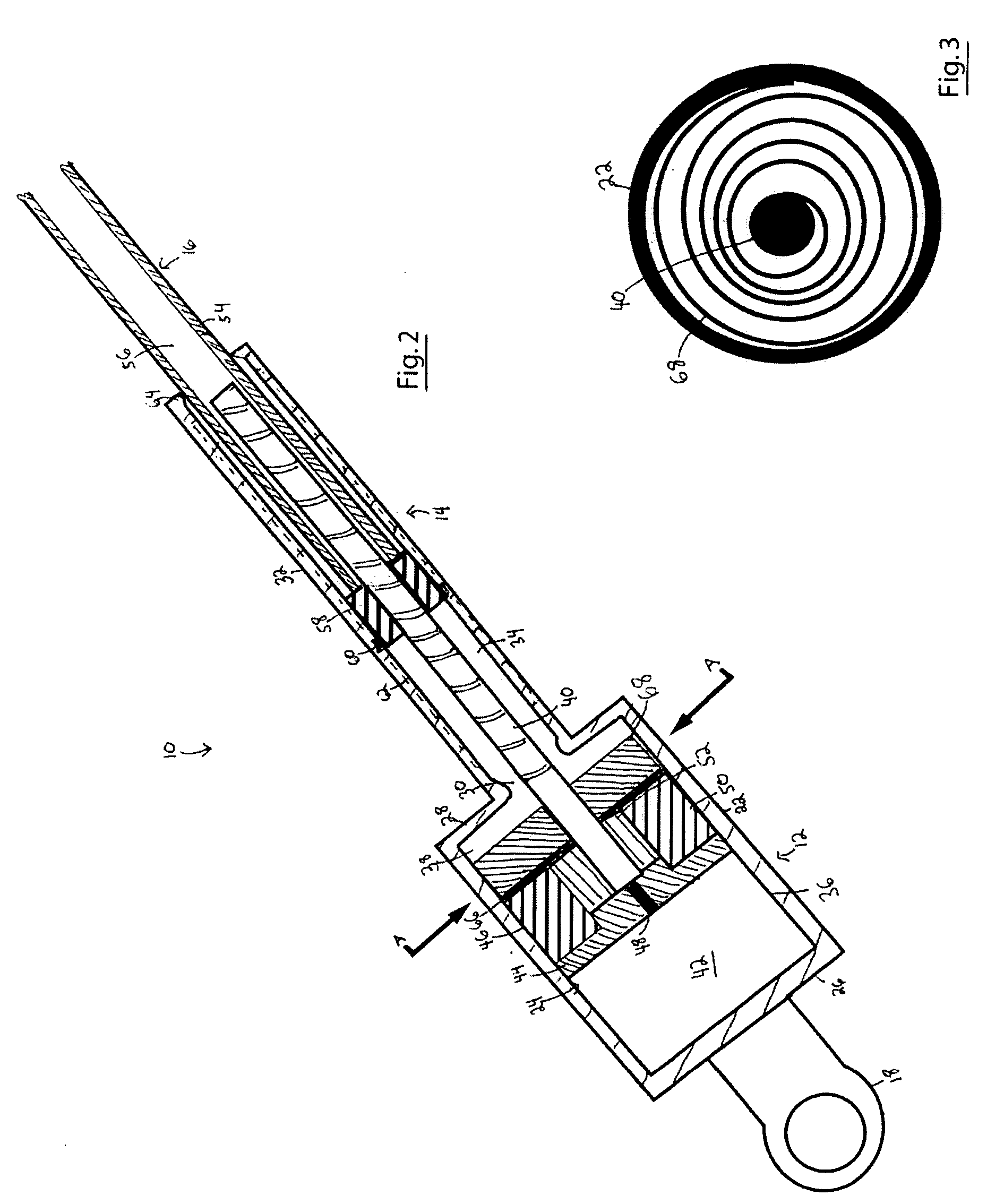
[0014] Referring now to FIG. 2, the interior of lower housing 12 is shown in greater detail. Lower housing 12 provides a cylindrical sidewall 22 defining a chamber 24. Pivot mount 18 is attached to an end wall 26 of lower housing 12 proximal to the vehicle body (not shown). Upper housing 14 provides a cylindrical sidewall 32 defining a chamber 34 that is open at both ends. A distal end wall 28 of lower housing 12 includes an aperture 30 ...


PUM


Abstract

An electromechanical strut using an inline motor coupled to an inline planetary gear that are both mounted in the lower housing. The motor-gear assembly drives a worm gear and nut screw in the upper housing, extending or retracting an extensible shaft. Additionally, a power spring mounted coaxially around the worm gear provides a mechanical counterbalance to the weight of a lift gate on the shaft. As the shaft extends, the power spring uncoils, assisting the motor-gear assembly in raising the lift gate. Retracting the shaft recoils the spring, storing potential energy. Thus, a lower torque motor-gear assembly can be used, reducing the diameter of the lower housing. Preferably, the power spring can also drive the power screw to extend the strut even when the motor-gear assembly is not engaged.

Description

FIELD OF THE INVENTION [0001] The present invention relates to an electrically-driven, mechanical strut. More specifically, the present invention relates to an electromechanical strut used to raise or lower an automotive lift gate. BACKGROUND OF THE INVENTION [0002] Lift gates provide a convenient access to the cargo areas of hatchbacks, wagons and other utility vehicles. Typically, the lift gate is hand operated, requiring manual effort to move the lift gate between the open and the closed positions. Depending on the size and weight of the lift gate, this effort can be difficult for some users. Additionally, manually opening or closing a lift gate can be inconvenient, particularly when the user's hands are full. [0003] Attempts have been made to reduce the effort and inconvenience of opening or closing a lift gate. One solution is to pivotally mount gas struts to both the vehicle body and the lift gate, reducing the force required for opening the lift gate. However, the gas struts ...

Claims


Application Information

Patent Timeline
Patent Type & Authority Applications(United States)
IPC IPC(8): B60J5/10
CPCE05F1/1008E05F1/1041E05Y2201/246E05Y2201/434E05F15/622E05Y2201/72E05Y2800/242E05Y2900/546E05Y2201/216E05Y2201/462
Inventor MITCHELL, STEPHEN A. G.
Owner MAGNA CLOSURES INC
Why Eureka
Try Eureka