
Printer

Inactive Publication Date: 2006-04-20
SEIKO INSTR INC
View PDF13 Cites 20 Cited by
  • Summary
  • Abstract
  • Description
  • Claims
  • Application Information

AI Technical Summary

Benefits of technology

[0030] Accordingly, when the sheet is the heat-sensitive adhesive label, the transport speed of the first transporting means is set faster than the transport speed of the second transporting means to secure a warp amount of a desired length or more which takes into account an expected time period for a cutting operation that follows, thus making it possible to cut the heat-sensitive adhesive label by the cutter device without stopping the transport of the heat-sensitive adhesive label by the second transporting means of the thermal activation device. Accordingly, malfunctions including an occurrence of paper jam caused by sticking of the heat-sensitive adhesive label onto the heating means can be solved, and in addition, extra maintenance such as discharging a label causing the paper jam becomes unnecessary. Hence, manufacturing efficiency of sticker labels can be significantly improved.
[0033] In the above-described printer, it is preferable that the first transporting means comprises a printing platen roller opposed to the printing means, and the second transporting means comprises a thermal activation platen roller opposed to the heating means, and that a pressing force with which the thermal activation platen roller is pressed toward the heating means during transporting of the ordinary label is set smaller than a pressing force applied during transporting of the heat-sensitive adhesive label. Therefore, no meandering or skewing occur while the ordinary label, which is thicker than the heat-sensitive adhesive label due to the release paper, is being transported, and the printing can be performed favorably on the label.

Problems solved by technology

However, to use this type of sticker label (hereinafter referred to as an “ordinary label”) as a label, it is necessary to peel off the release paper from the adhesive layer, and accordingly, there is a disadvantage in that wastes inevitably occur.
As a result, the heat-sensitive adhesive layer that has started to exhibit its adhesiveness is undesirably stuck onto the thermal-activation thermal head 52 (heater elements 51), and the heat-sensitive adhesive label 60 is not smoothly transported even if the transport is resumed, causing malfunctions such as occurrence of so-called paper jam or transport failure.
There is another problem in that heat from the heater elements 51 is transmitted to the printable layer (heat-sensitive color-developing layer) of the heat-sensitive adhesive label, thus developing this layer.
For this reason, a printer body is enlarged, and applications of the printer become limited.
However, though this method is suitable in the case of the heat-sensitive adhesive label, two problems as will be described below are expected to occur when applying this method to an ordinary label (one in which a sheet label is stuck onto the release paper).
2) The release paper is heated by the thermal-activation thermal head 52, causing danger in handling.

Method used


Image

  • Printer
  • Printer
  • Printer

Examples


Embodiment Construction

[0047] An embodiment of the present invention will now be described with reference to the drawings.

(Configuration of Printer)

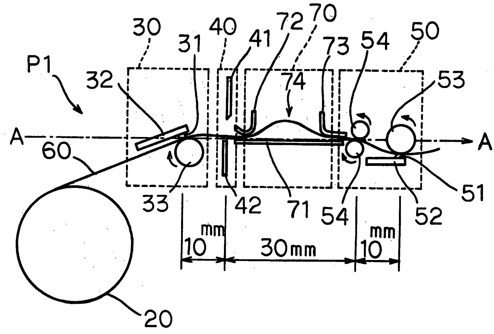
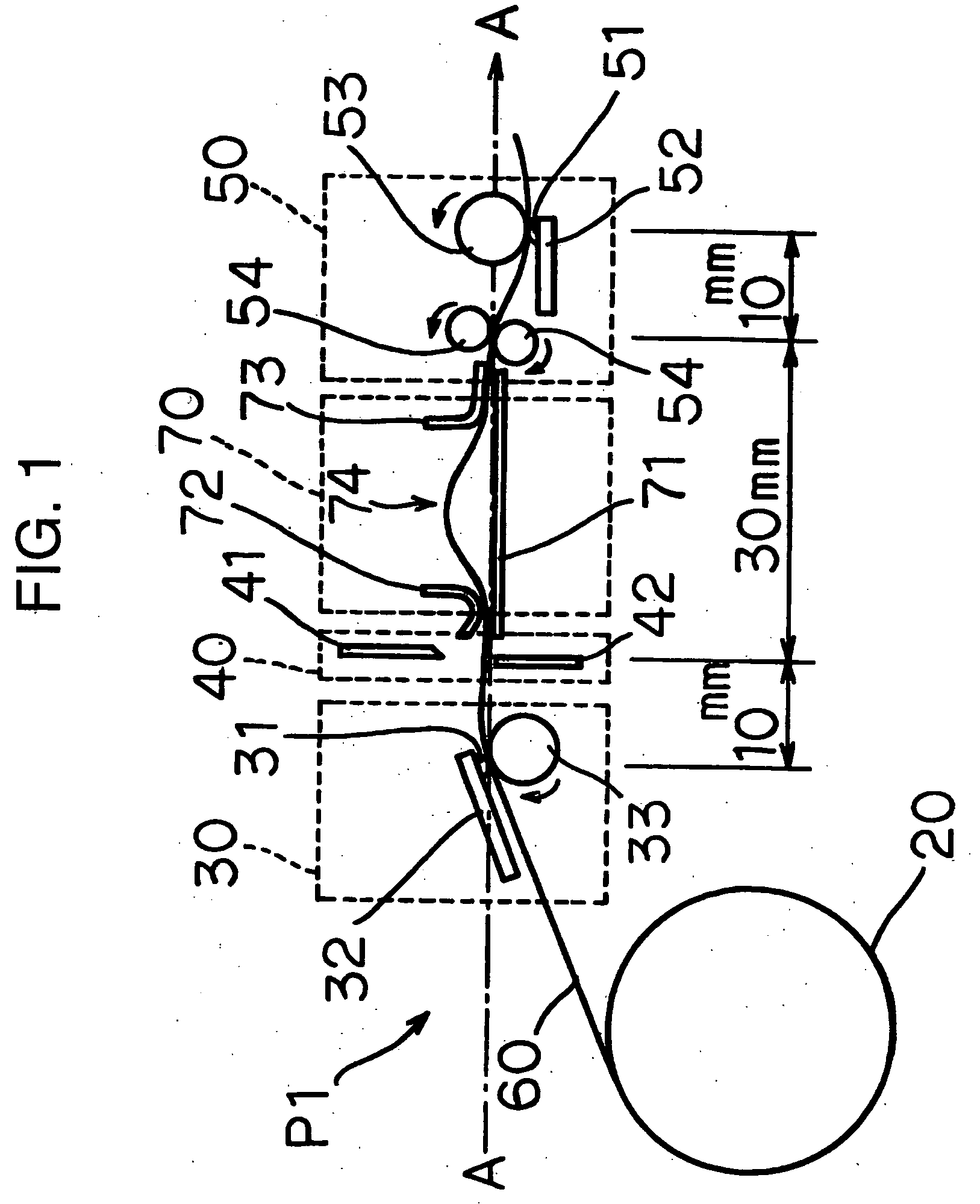
[0048]FIG. 1 is a schematic view showing a configuration of a thermal printer 1 as the embodiment of the present invention.

[0049] The thermal printer P1 is an apparatus usable for both of a heat-sensitive adhesive label and an ordinary label.

[0050] This printer apparatus is composed of a roll housing unit 20 which holds a tape-like heat-sensitive adhesive label 60 and a tape-like ordinary label (not shown), each of which is wound in a roll shape, such that those labels are exchangeable, a printing unit 30 which prints on the heat-sensitive adhesive label 60 or the ordinary label which is held in the roll housing unit 20, a cutter unit 40 which cuts the heat-sensitive adhesive label 60 or the ordinary label into pieces with a predetermined length, a thermal activation unit 50 as a thermal activation device which functions only in the case where the heat-se...


PUM

PropertyMeasurementUnit
Forceaaaaaaaaaa
Speedaaaaaaaaaa
Sensitivityaaaaaaaaaa

Abstract

Provided is a printer capable of performing printing on both of a heat-sensitive adhesive label and an ordinary label in which release paper is stuck onto an adhesive surface. A thermal printer is composed of a roll housing unit which holds a tape-like heat-sensitive adhesive label and a tape-like ordinary label, each of which is wound in a roll shape, such that those labels are exchangeable, a printing unit which prints on the heat-sensitive adhesive label or the ordinary label which is held in the roll housing unit, a cutter unit which cuts the heat-sensitive adhesive label or the ordinary label into pieces with a predetermined length, a thermal activation unit which functions only in a case where the heat-sensitive adhesive label is held in the roll housing unit and thermally activates a heat-sensitive adhesive layer of the heat-sensitive adhesive label, a guide unit which guides the heat-sensitive adhesive label from the cutter unit to the thermal activation unit, a control unit which controls the above-described respective units to operate differently between a case of using the ordinary label and a case of using the heat-sensitive adhesive label, and the like.

Description

BACKGROUND OF THE INVENTION [0001] 1. Field of the Invention [0002] The present invention relates to a printer capable of recording on a sheet material having, on one side, a thermally activated adhesive surface which exhibits adhesive strength when heated, and on a sheet material having, on one side, an adhesive surface to which release paper is affixed. [0003] 2. Description of the Related Art [0004] In recent years, many of sticker labels used for indication of a bar code, a price, and so on, are of a type having an adhesive layer on a backside of a recording surface (print surface) and stored in a state where a mount or release paper (liner) is affixed thereon for temporary adhesion. However, to use this type of sticker label (hereinafter referred to as an “ordinary label”) as a label, it is necessary to peel off the release paper from the adhesive layer, and accordingly, there is a disadvantage in that wastes inevitably occur. [0005] In this connection, as a system which does n...

Claims


Application Information

Patent Timeline
IPC IPC(8): B41J2/325
CPCB41J2/325
Inventor SANBONGI, NORIMITSUHOSHINO, MINORUOBUCHI, TATSUYASATO, YOSHINORI
Owner SEIKO INSTR INC
Learn More