However, conventional methods are generally configured to measure only a
single point at a time, and therefore, these systems are both time and resource intensive.
Techniques such as Moiré
Interferometry,
Fourier Transform Profilometry, and other grid projection methods require that an entire image (or many entire images) of the surface be analyzed to measure the 3-dimensional position of even one point on the surface, which increases
data acquisition and analysis time.
Moreover, if there is a discontinuous step in the surface, there will be a corresponding jump in the
grid pattern and it may be impossible to uniquely identify gridlines across this discontinuity so that accurate measurements cannot be made.
Therefore, although these methods are appealing, the resources required to analyze the entire image surface in a 3-dimensional manner make these methods generally impracticable.
However, patterns from these types of techniques are generally difficult to interpret, and further, surface discontinuities in the object are known to result in ambiguous measurements when these techniques are employed.
Conventional
structured light techniques generally require that the optical
projection system and the camera
system be placed in precise alignment, which causes difficulty if the
system becomes misaligned, as can easily happen.
These precise processes and movements are expensive to generate, operationally slow, and very often require data collection for areas that are not of interest.
The simplicity of basic
triangulation typically makes it the technique of choice for automated inspection systems, as the more complex techniques require calculations too lengthy for real-time application and usually involve a level of user interpretation of the data for all but the simplest surfaces.
Complex surfaces are also difficult to efficiently measure with automated 3-dimensional techniques.
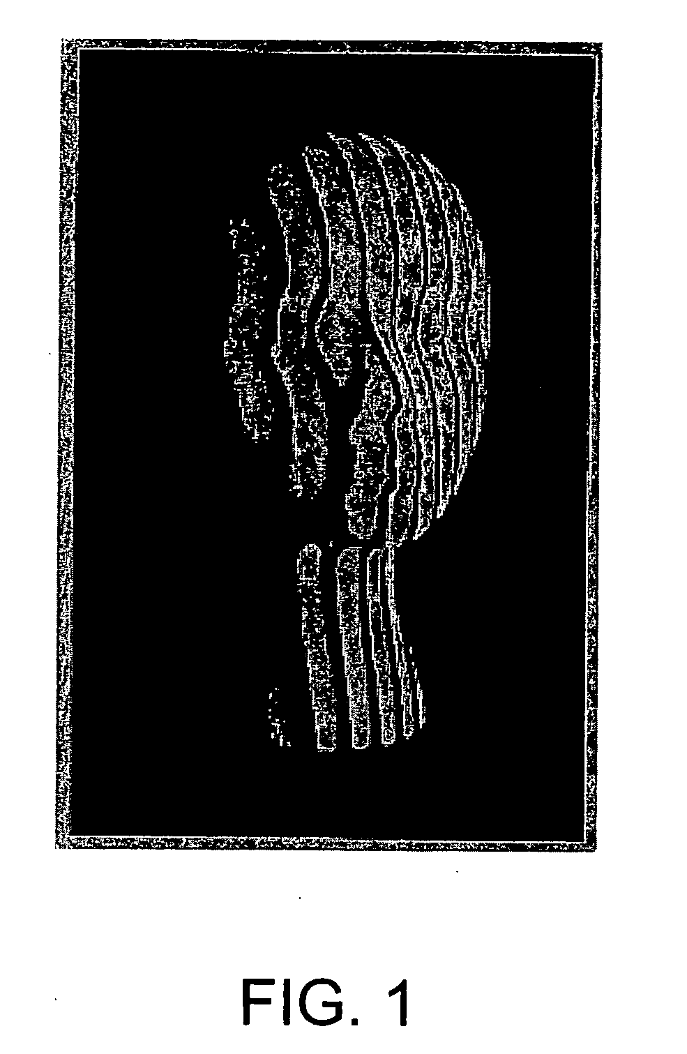
Large surface discontinuities generally result in discontinuities in the
grid pattern (or the “interference” pattern) that are almost impossible for
machine vision systems to interpret autonomously, despite the use of complicated grid phase-shifting techniques and advanced fringe-
processing algorithms.
Even in the case of
triangulation, surfaces with sharp edges and large jumps between surfaces can be problematic due to the requirement of having to uniquely identify each grid line in the image.
If exact identification of a grid line is not possible, then the physical position of that line in the original grid remains unknown to the system, and that portion of the measurement incomplete.
Therefore, in this situation the resulting
triangulation calculation is generally unable to correctly determine the height or surface profile of the surface being measured.
Obviously, this is a complex solution that is difficult to implement in an autonomous, real-
time system, as several images must be acquired and precisely aligned with each other.
However, this method has several disadvantages, which include the need to synchronize the LCD
frame rate to the camera
frame rate to ensure accurate recording of the time-varying pixels, and the fact that the field-of-view versus resolution trade-off (as well as the system cost) are all driven by the size and number of pixels in the LCD panel.
However, Moire-type fringe methods require precise non-uniform type motion in moving the grating, require complicated fringe identification algorithms, and the entire image must be recorded to map even one point.
Therefore, Moire-type methods are generally undesirable as a result of these additional requirements.
However, reported use of this technique generally indicates that it is very limited in its technical capabilities.
A method of scanning this point would be required to measure the entire surface, which would make the system extremely slow.
The data was analyzed with analog
electronics by measuring the frequency of the grid-crossings, which is complicated by the fact that the received
optical intensity is actually a frequency-modulated
signal with a pseudo-
sine wave carrier instead of a simple, single-frequency
signal.
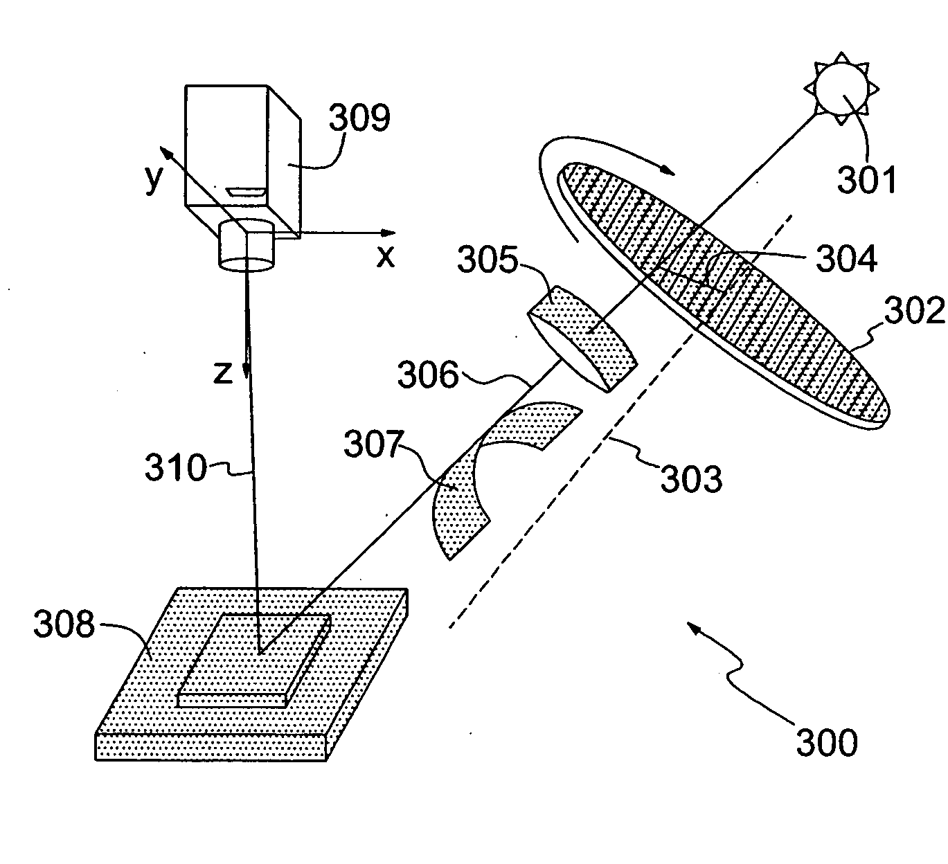
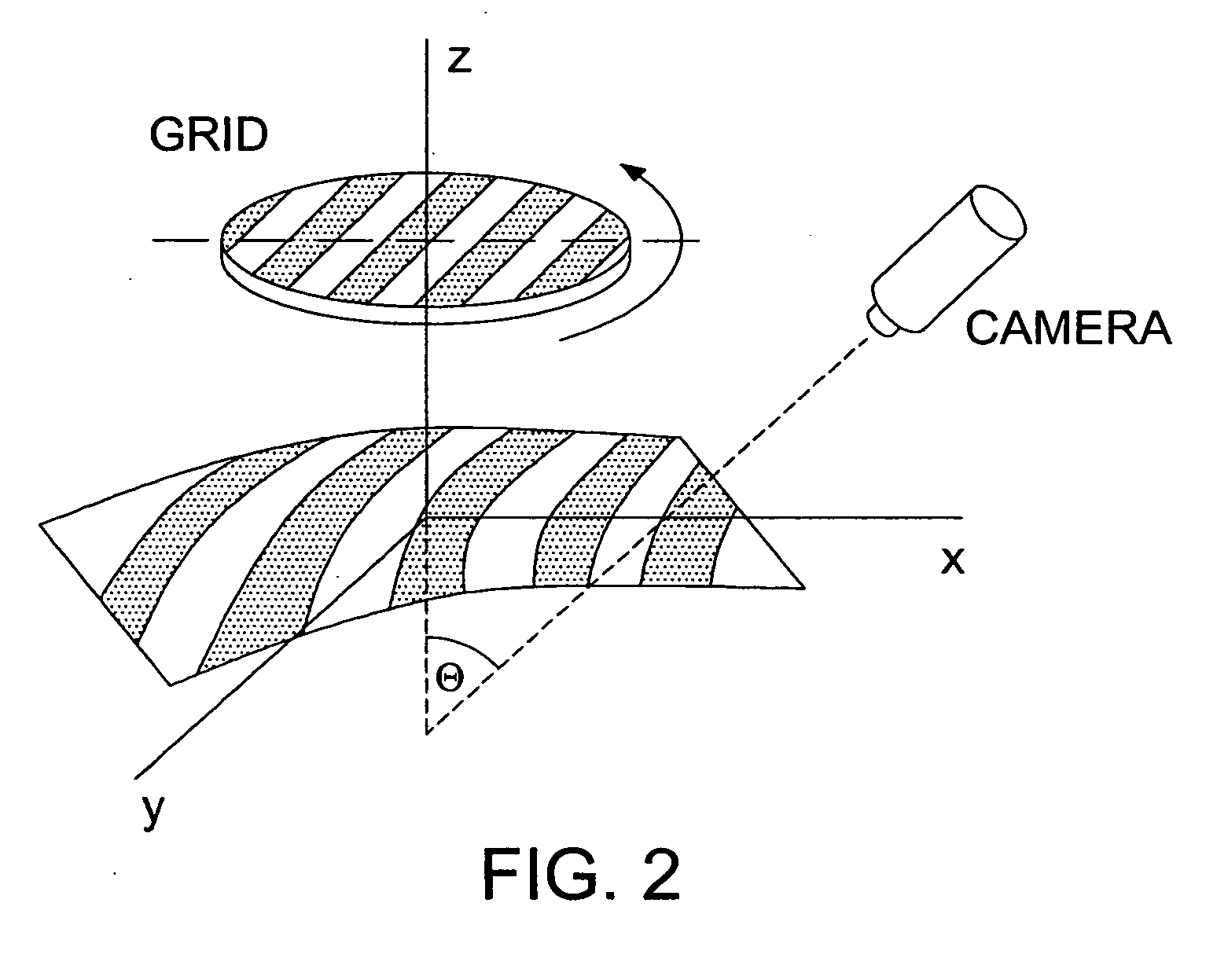
A second problem is that the method given to calculate the surface profile requires precise knowledge of the position and orientation of the grid
projection system and the imaging camera used.
Therefore, in view of the disadvantages presented by conventional surface profiling systems and methods, there is a need for an optical, non-
contact method for conducting surface profiling that is capable of simultaneously measuring an array of points on the surface of an object.

