

Optical terminal apparatus
a technology of optical terminals and terminals, which is applied in the field of optical terminals, can solve the problems of large-scale apparatuses, large number of pumping light sources, and limited wavelength bands which can be substantially used,
- Summary
- Abstract
- Description
- Claims
- Application Information
AI Technical Summary
Benefits of technology
Problems solved by technology
Method used
Image

Examples
first embodiment
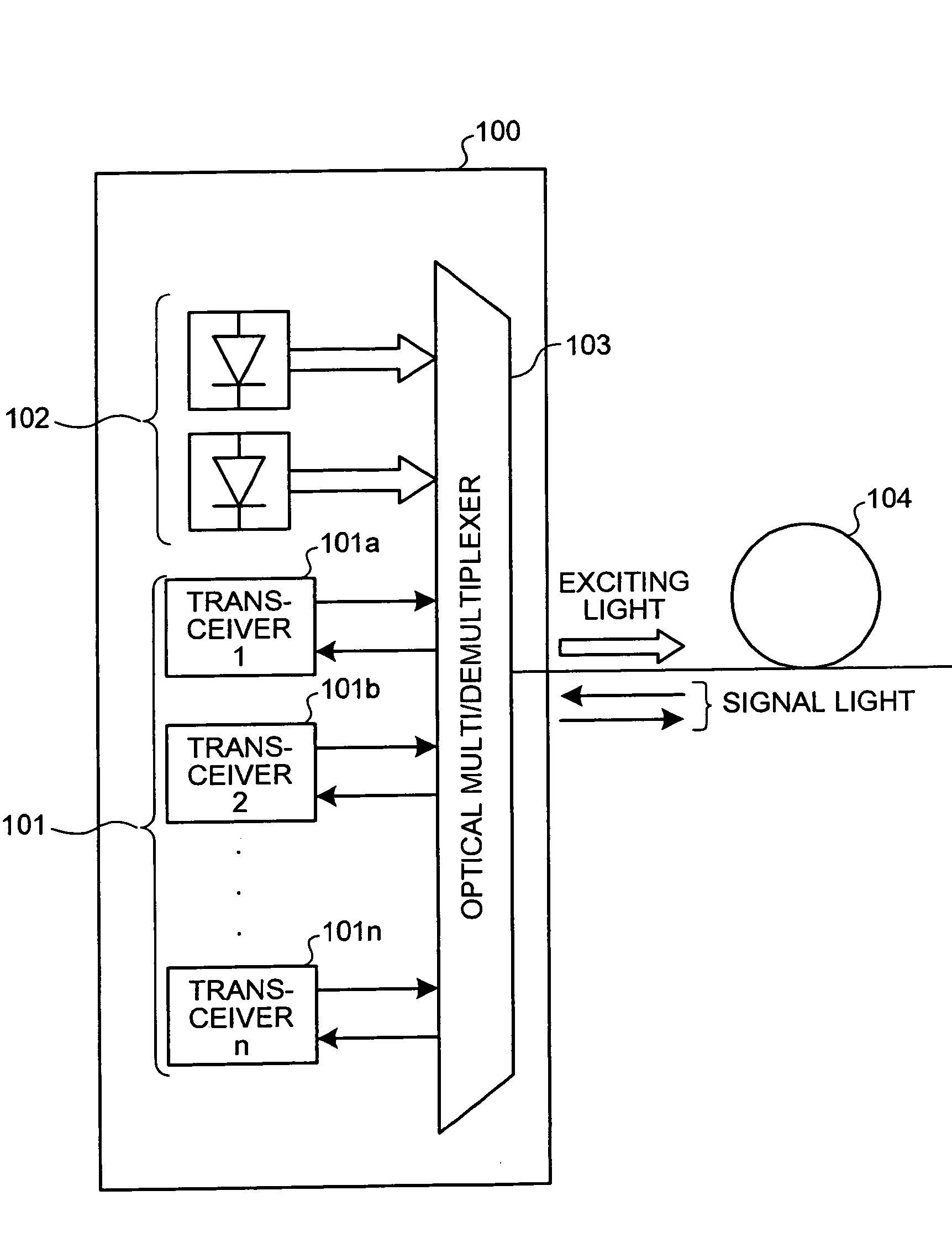
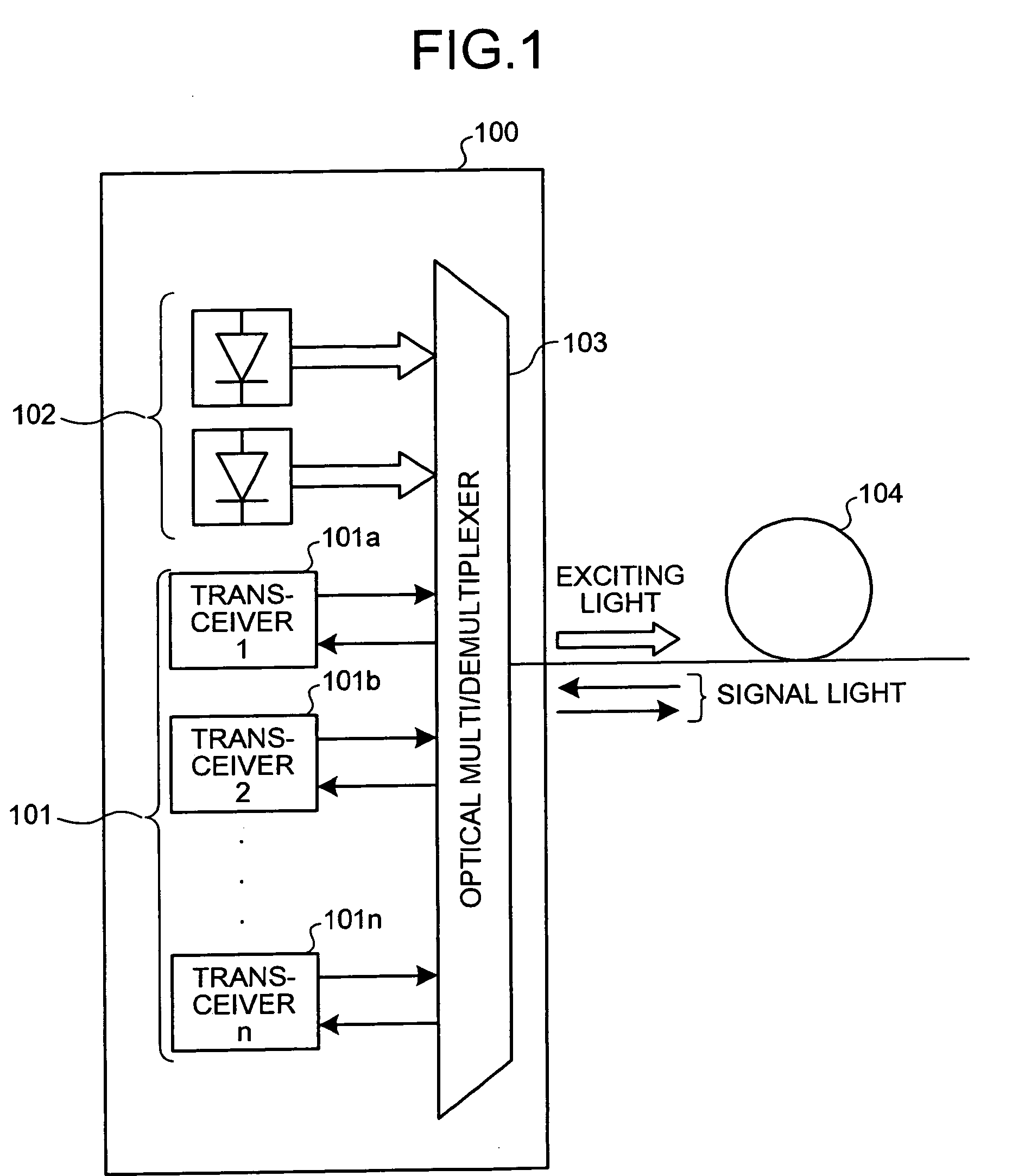
[0039]FIG. 1 is a diagram of a basic configuration of an optical terminal apparatus according to the An optical terminal apparatus 100 shown in FIG. 1 includes transceivers 101 (101a to 101n) which transmit and receive signal lights, a pumping light source 102 which supplies a pumping light to perform Raman amplification, and an optical multiplexer / demultiplexer 103. The optical terminal apparatus 100 transmits and receives a signal light through a transmission path (optical transmission path) 104 constituted by an optical fiber.
[0040] The optical multiplexer / demultiplexer 103 multiplexes wavelengths of signal lights having different wavelengths and output from the transceivers 101, outputs the multiplexed signal light to the transmission path 104, and demultiplexes the wavelength of a WDM light received from the transmission path 104. An arrow in FIG. 1 indicates a light traveling direction, an arrow in solid line indicates a signal light, and a heavy-line blank arrow indicates a ...
second embodiment
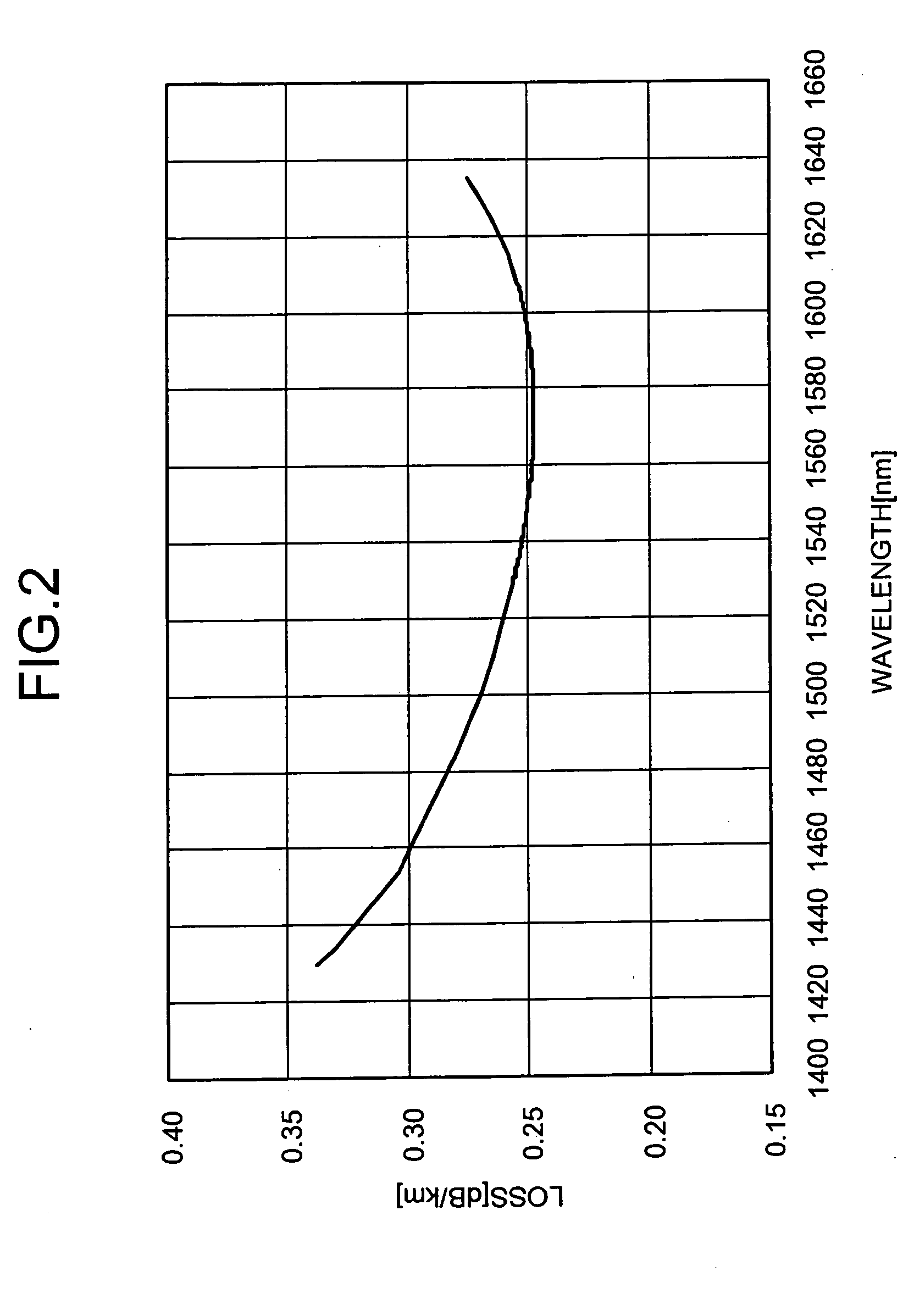
[0116] an optical terminal apparatus which includes a unit for an EDFA therein to amplify a signal light will be described below. The EDFA is an optical amplifier in which a pumping light is input to an optical fiber having a core section doped with erbium (Er) which is a rare earth to cause induced emission of a light of a wavelength in a 1550-nm band so that a signal light transmitted to an EDF section is amplified. Therefore, as a signal light to be amplified, a light having a wavelength of 1530 nm to 1590 nm selected from wavelengths at which wavelength dependence losses are small in FIG. 2 is used in consideration of an amplification gain band of the EDFA. On the basis of the energy level of an erbium ion (Er3+), a light having a wavelength of 1480 nm or 980 nm is used as a pumping light to cause inductive emission.
[0117]FIG. 12 is a diagram of a configuration of an optical terminal apparatus according to the second embodiment. An optical terminal apparatus 1200 includes a tra...
third embodiment
[0169]FIG. 18 is a diagram of a basic configuration of an optical terminal apparatus according to the An optical terminal apparatus 1800 is constituted by a transceiver 1201, a transceiver 1202, a transceiver 1203, and an optical multiplexer / demultiplexer 1205. The transceiver 1201 incorporates an optical multiplexer / demultiplexer, and can be replaced with the unit of an EDFA. In the transceiver 1202 and the transceiver 1203, multiplexing / demultiplexing is performed by the optical multiplexer / demultiplexer 1205.
[0170] Similarly, an optical terminal apparatus 1810 includes a transceiver 1211, a transceiver 1212, a transceiver 1213, and an optical multiplexer / demultiplexer 1215. The transceiver 1211 incorporates an optical multiplexer / demultiplexer, and can be replaced with the unit of an EDFA. In the transceiver 1212 and the transceiver 1213, multiplexing / demultiplexing is performed by the optical multiplexer / demultiplexer 1215. The transceiver 1201 to the transceiver 1203 and the t...
PUM
 Abstract
Description
Claims
Application Information