Packet analysis system

Inactive Publication Date: 2006-04-20
YOKOGAWA ELECTRIC CORP
View PDF9 Cites 106 Cited by
  • Summary
  • Abstract
  • Description
  • Claims
  • Application Information

AI Technical Summary

Benefits of technology

[0051] Further, since the server integrates the classification information provided by each terminal node type se

Problems solved by technology

Thus, to determine whether one packet is based on “worm (program which grows without infecting another program) A” or “worm B” or whether or not one packet is port scan, it is important to know the association between the packets; in the

Method used


Image

  • Packet analysis system
  • Packet analysis system
  • Packet analysis system

Examples


Embodiment Construction

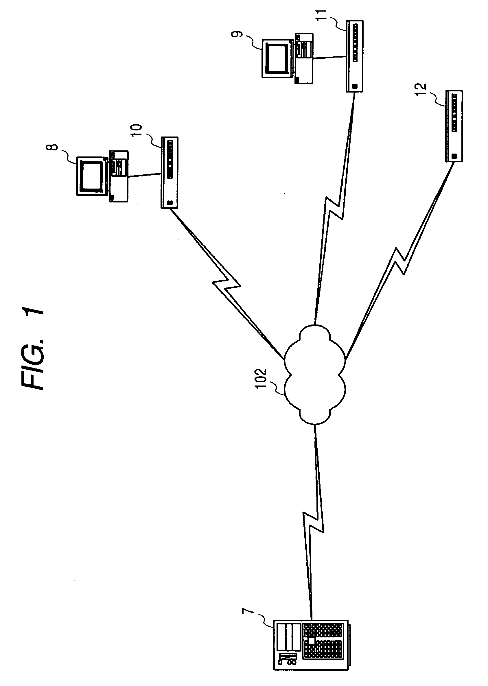
[0082] An embodiment of the invention will be discussed in detail with the accompanying drawings. FIG. 1 is a block diagram to show the configuration of an embodiment of a packet analysis system according to the invention.

[0083] In FIG. 1, numeral 7 denotes a server which generates a whole report (a log file) of the packet analysis system, numerals 8 and 9 denote computers, numerals 10, 11, and 12 denote terminal node type sensors which are connected to the computers or installed solely at a plurality of locations, and capture propagating packets and classify the captured packets in association with each other, and numeral 102 denotes a general-purpose network such as the Internet.

[0084] The server 7 is connected to the network 102, and the terminal node type sensors 10, 11, and 12 are also connected to the network 102. The computers 8 and 9 are connected to terminals of the terminal node type sensors 10 and 11.

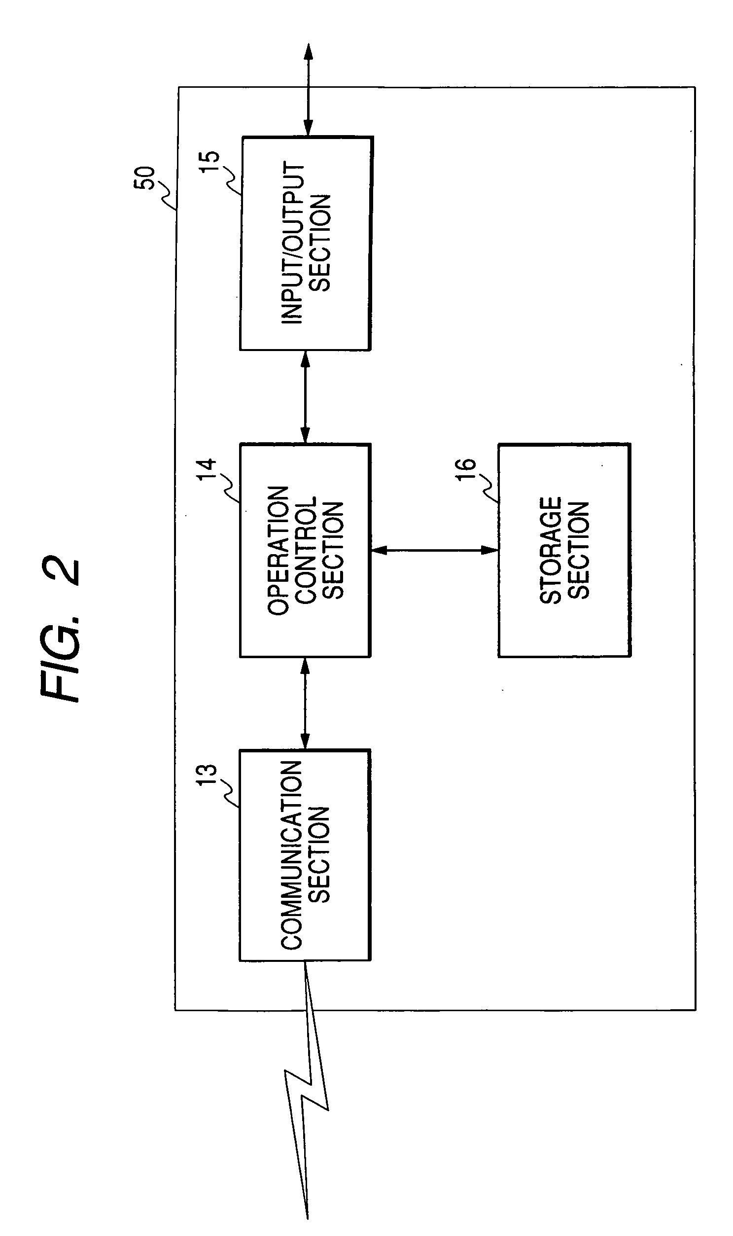
[0085]FIG. 2 is a block diagram to show the configuration of a specif...


PUM


Abstract

A packet analysis system captures packets propagating through a network, and analyzes the captured packets. The packet analysis has a plurality of terminal node type sensors and a server. Each of the terminal node type sensors captures packets propagating through the network, and classifies the captured packets. A server acquires classification information from at least one of the terminal node type sensors through the network, and generates a whole report of the packet analysis system based the acquired classification information.

Description

CROSS-REFERENCE TO RELATED APPLICATIONS [0001] This application is based upon and claims the benefit of priority from the prior Japanese Patent Applications No. 2004-303857, filed on Oct. 19, 2004, the entire contents of which are incorporated herein by reference. BACKGROUND OF THE INVENTION [0002] 1. Field of the Invention [0003] This invention relates to a packet analysis system for capturing packets propagating through a network such as the Internet and analyzing the captured packets, and in particular relates to a packet analysis system that can separate an access variation hard to separate. [0004] 2. Description of the Related Art [0005] JP-A-2002-185539, JP-A-2003-204358 and JP-A-2003-273936 are referred to as related art relevant to a packet analysis system for capturing packets propagating through a network such as the Internet and analyzing the captured packets. [0006]FIG. 24 is a block diagram to show a configuration example of such a packet analysis system in a related ar...

Claims


Application Information

Patent Timeline
IPC IPC(8): G06F15/173H04J1/16G06F13/00H04L69/40
CPCH04L43/12H04L43/18
Inventor BABA, SHUNSUKESUZUKI, KAZUYATANAKA, TAKASHI
Owner YOKOGAWA ELECTRIC CORP
Why Eureka
Try Eureka