
Selectable state machine user interface system

Inactive Publication Date: 2006-04-20
MICROSOFT TECH LICENSING LLC
View PDF57 Cites 88 Cited by
  • Summary
  • Abstract
  • Description
  • Claims
  • Application Information

AI Technical Summary

Benefits of technology

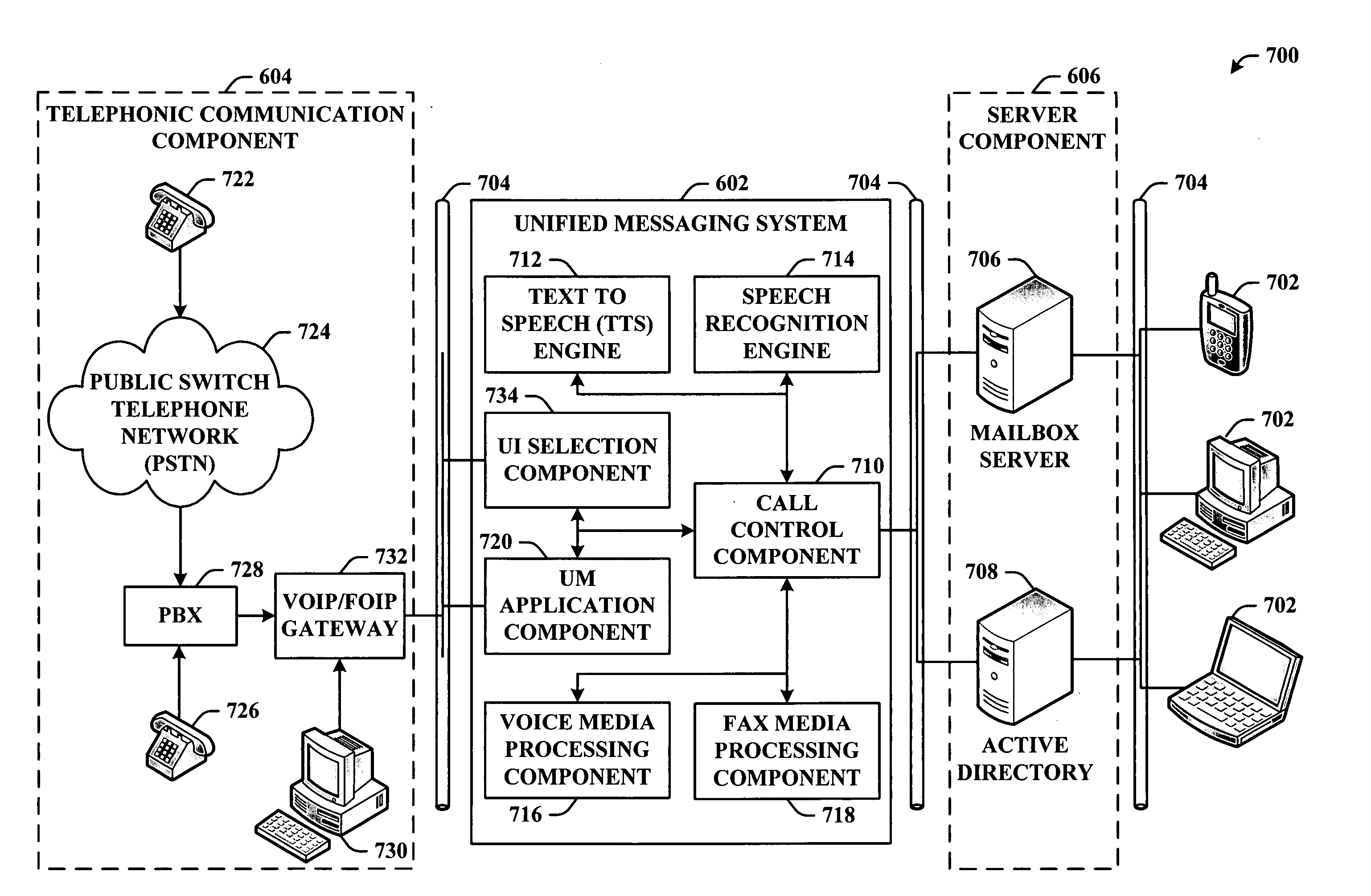
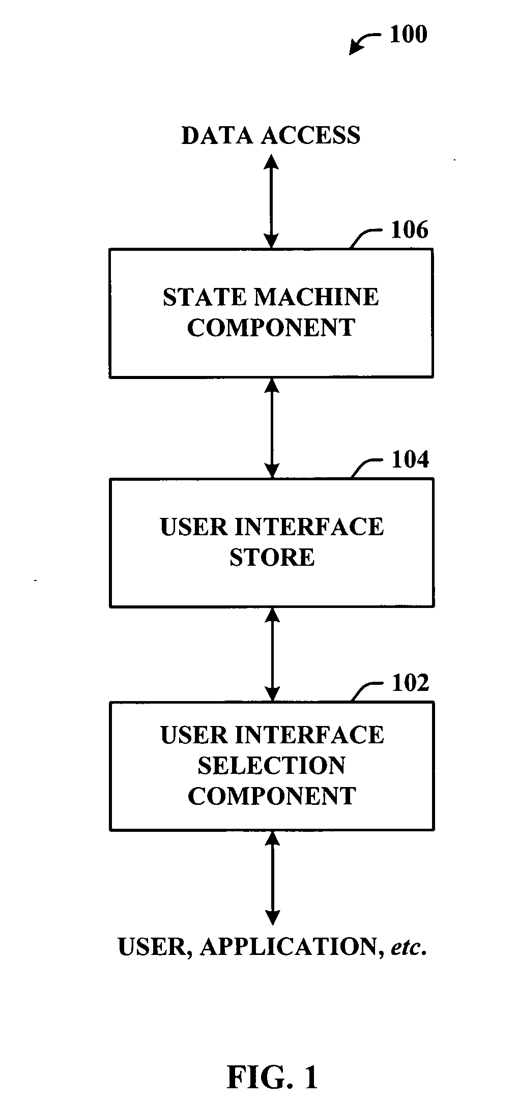
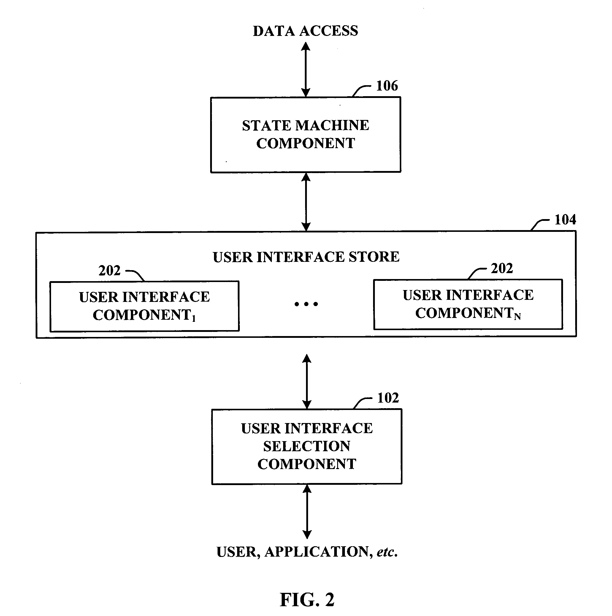
[0011] Navigation and flow control (e.g., state transitions) in the state machine can be leveraged by multiple user interface (UI) mechanisms that co-exist actively. The invention introduces speech recognition features together with other input mechanisms to drive the user interface of an application state machine (e.g., a unified messaging system (UM)). In accordance with an aspect of the invention, the speech recognition UI is designed to provide a natural navigation through the application independent of a DTMF user interface. The user can navigate through the speech menu without having to enter any DTMF data.
[0017] Each speech menu can also have menu commands that are specific to the menu context. For example, with access to an application programming interface, the invention can add functionality to enable telephonic generation and retrieval of email communications. The invention can further facilitate accepting or canceling calendar items (e.g., meeting requests and appointments) via a telephonic communications device.

Problems solved by technology

This is often cumbersome and very time consuming.
For example, a user is frequently addressed with a specific prompt such as, “please enter your password” or “press one to review all new messages.” While these audible prompts are sometimes useful, they tend to be time consuming and, nonetheless, often still require the user to employ DTMF techniques via a keypad.
These efforts have been very limited in that they only recognize preprogrammed menu selections and / or data.
Despite which technique is provided, state machines today are limited to employing a single navigational technique at any given time.
However, with respect to these systems, both options are usually not simultaneously or concurrently available and the user does not have the option of toggling between the navigational systems during any one session.

Method used


Image

  • Selectable state machine user interface system
  • Selectable state machine user interface system
  • Selectable state machine user interface system

Examples


Embodiment Construction

[0042] The subject invention is now described with reference to the drawings, wherein like reference numerals are used to refer to like elements throughout. In the following description, for purposes of explanation, numerous specific details are set forth in order to provide a thorough understanding of the subject invention. It may be evident, however, that the subject invention can be practiced without these specific details. In other instances, well-known structures and devices are shown in block diagram form in order to facilitate describing the subject invention.

[0043] As used in this application, the terms “component” and “system” are intended to refer to a computer-related entity, either hardware, a combination of hardware and software, software, or software in execution. For example, a component can be, but is not limited to being, a process running on a processor, a processor, an object, an executable, a thread of execution, a program, and / or a computer. By way of illustrat...


PUM


Abstract

A system that concurrently provides multiple user interface (UI) mechanisms that facilitate control of an application state machine (e.g., unified message system). More particularly, the invention can create two relatively distinct user experiences, one via dual tone multi-frequency (DTMF) navigation and another through speech recognition navigation of a unified message system. In accordance therewith, one single underlying state machine can be used. Navigation and flow control (e.g., state transitions) in the state machine can be leveraged by multiple UI mechanisms that actively co-exist. The invention introduces speech recognition features together with other input mechanisms to drive the UI of an application state machine (e.g., unified messaging system). The speech recognition UI can be designed to provide a natural navigation through the application independent of a DTMF UI.

Description

CROSS-REFERENCE TO RELATED APPLICATIONS [0001] This application claims the benefit under 35 U.S.C. § 119(e) of U.S. Provisional Patent application Ser. No. 60 / 620,826 entitled “Unified Messaging System” and filed on Oct. 20, 2004, the entirety of which is incorporated by reference herein.TECHNICAL FIELD [0002] This invention is related to messaging systems and more particularly to a selectable user interface system that can employ variable interactive mechanisms to navigate through and control an underlying application state machine. BACKGROUND OF THE INVENTION [0003] A state machine is a computing device designed with the operational states required to perform a particular task or to solve a specific problem. There are countless special-purpose devices built as state machines. A voicemail system is an example of such an application state machine. [0004] Today, many state machines, and particularly voicemail systems, employ a dual tone multi-frequency (DTMF) navigational technique t...

Claims


Application Information

Patent Timeline
IPC IPC(8): H04M1/64G10L15/00H04M1/72433H04M1/72469
CPCG10L15/26H04M3/42204H04M3/4931H04M3/5307H04M3/533H04M3/53333H04M2201/39H04M2201/40H04M2203/254H04M2203/4509A21B5/023A21B3/133A47J37/01
Inventor HOWELL, DAVID A.FONG, DAVID T.
Owner MICROSOFT TECH LICENSING LLC
Learn More