

Injection molded article
- Summary
- Abstract
- Description
- Claims
- Application Information
AI Technical Summary
Benefits of technology
Problems solved by technology
Method used
Image

Examples
first embodiment
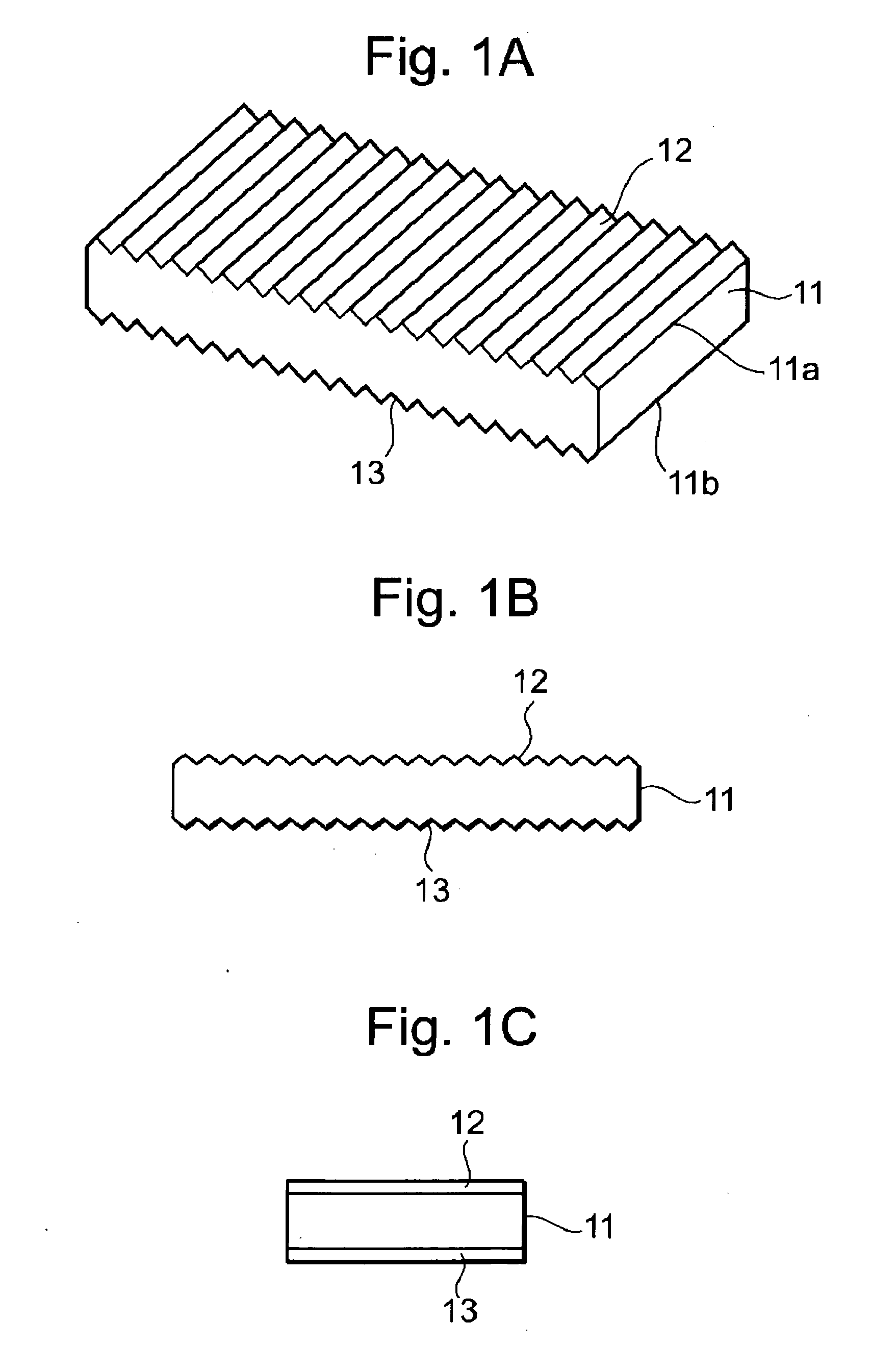
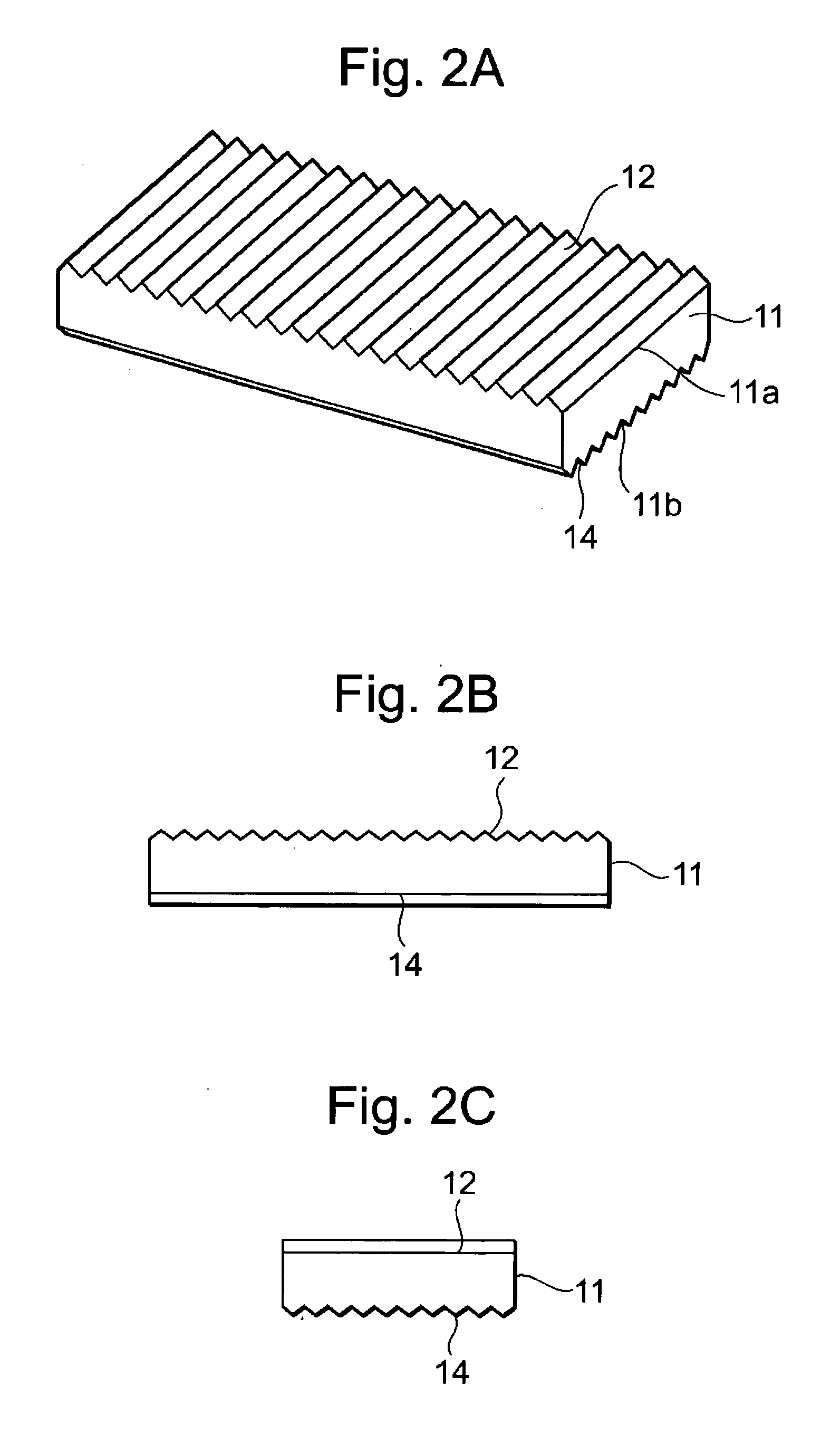
[0056] In the present invention, a plurality of periodically repeated undulations are formed on the surface (front surface) of a molded article made by injection molding of a resin. Moreover, a plurality of periodically repeated undulations corresponding to the above-described undulations are formed on a back surface. The undulations of the front and back surfaces are formed at a time of the injection molding of the molded article. FIGS. 1A to 3D show configurations in the present invention. In these configurations, the injection molded article has a flat plate shape, and a plurality of undulations are formed on the opposing surfaces of the article.
[0057] In a first configuration of FIGS. 1A to 1C, a plurality of periodically repeated undulations 12 are formed in such a manner as to continue in a longitudinal direction on an upper surface 11a which is a first surface of a molded article 11 having a flat plate shape. Furthermore, a plurality of periodically repeated undulations 13 co...
second embodiment
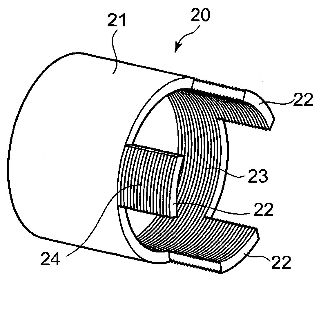
[0066] The light intercepting ridges 23 are formed on the inner peripheral surface of each extended portion 22, and the pseudo light intercepting ridges 24 are formed on the outer peripheral surface at the injection molding time of the lens barrel 20. Consequently, since a resin temperature distribution on an inner peripheral side of the extended portion 22 is substantially the same as that on an outer peripheral side, no difference of a molding shrinkage of the resin is generated, and no warpage is generated in the extended portion 22. Especially in the second embodiment, since the extended portion 22 is a cantilever beam portion, warpage may be easily generated during the injection molding, but the warpage can be prevented, when the pseudo light intercepting ridges 24 corresponding to the light intercepting ridges 23 are formed.
[0067]FIG. 5 shows a lens barrel 20A in which any pseudo light intercepting ridge 24 is not formed on the extended portions 22. In this case, the warpage i...
third embodiment
[0068]FIGS. 6A and 6B show the present invention. In this third embodiment, the present invention is applied to a finder frame 30 of a camera.
[0069] The finder frame 30 has a U-shaped frame member 31, and light intercepting ridges 33 are formed on an inner surface of the member. The frame member 31 has a pair of facing pieces, and a transversely long opening 35 is formed in one of facing pieces 32. The opening 35 is formed in such a manner as to be positioned in the middle of the facing piece 32 in a height direction. An end portion (upper end portion) 32a of the facing piece 32 above the opening 35 on a free side is a center impeller beam portion in which warpage may be easily generated.
[0070] The light intercepting ridges 33 are formed on the whole inner surfaces of the facing pieces 32, and the light intercepting ridges 33 are therefore formed also on the upper end portion 32a. In this third embodiment, pseudo light intercepting ridges 34 are formed on the outer surface that is ...
PUM
| Property | Measurement | Unit |
|---|---|---|
| Shape | aaaaa | aaaaa |
Abstract
Description
Claims
Application Information