
Solid oxide fuel cell and method for producing same

a fuel cell and solid oxide technology, applied in the direction of fuel cell details, cell components, electrochemical generators, etc., can solve the problems of reducing the power density of the cell, affecting the output power of the cell, and affecting the production efficiency of the cell

Inactive Publication Date: 2006-04-20
PANASONIC CORP
View PDF2 Cites 32 Cited by
  • Summary
  • Abstract
  • Description
  • Claims
  • Application Information

AI Technical Summary

Benefits of technology

[0016] Furthermore, the present invention provides a method for manufacturing a solid oxide fuel cell including an anode containing an anode catalyst, a cathode, and a first solid oxide held between the anode and the cathode, the method comprising:
[0017] (I) a step o

Problems solved by technology

However, ceramics are characterised by susceptibility to thermal stress and physical shock.
However, merely lowering the power generation temperature decreases the power density of the cell.
However, when a porous cermet in which nickel particles and solid oxide are mixed is used, the output power tends to drop significantly at temperatures lower than 600° C. It seems that a decrease in the catalytic activity is the main factor for this, and although many attempts have been made to improve the catalytic activity through the optimization of the porosity and the composition ratio of the anode, satisfactory results have not been obtained.
As a substitute for nickel particles, a cermet mixed with platinum particles that have superior catalytic activity at low temperatures than the nickel particles has been considered, but because it is necessary to include a large quantity of expensive platinum in the cermet, there are issues regarding the cost.

Method used


Image

  • Solid oxide fuel cell and method for producing same
  • Solid oxide fuel cell and method for producing same
  • Solid oxide fuel cell and method for producing same

Examples


working examples

[0095] The present invention is explained in further detail below using the working examples. It should be noted that the present invention is not limited to the working examples shown below.

[0096] In the working examples, fuel cells were fabricated (sample 1 to sample 20) using the methods shown below and power generation characteristics (power generation temperature dependence) of each fuel cell were evaluated. First, a method for fabricating a sample is shown. It should be noted that sample 20 is a conventional fuel cell and is a comparative example.

Sample 1

[0097] First, a laminated body of a cathode and a first solid oxide was formed.

[0098] First, a paste containing LaMnO3 particles with an average particle diameter of 5 μm or less, Ce0.9Gd0.1O2 particles with an average particle diameter of 5 μm or less, and carbon powder with an average particle diameter of 10 μm (manufactured by Nippon Carbon Co., Ltd.) was made up by mixing the materials noted above, and further adding ...


PUM

PropertyMeasurementUnit
Temperatureaaaaaaaaaa

Abstract

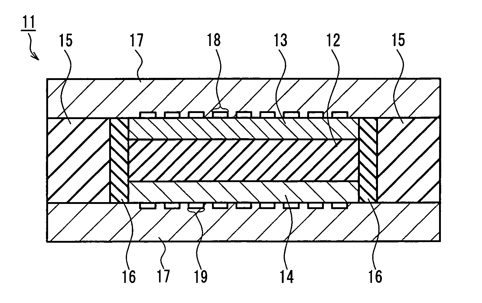
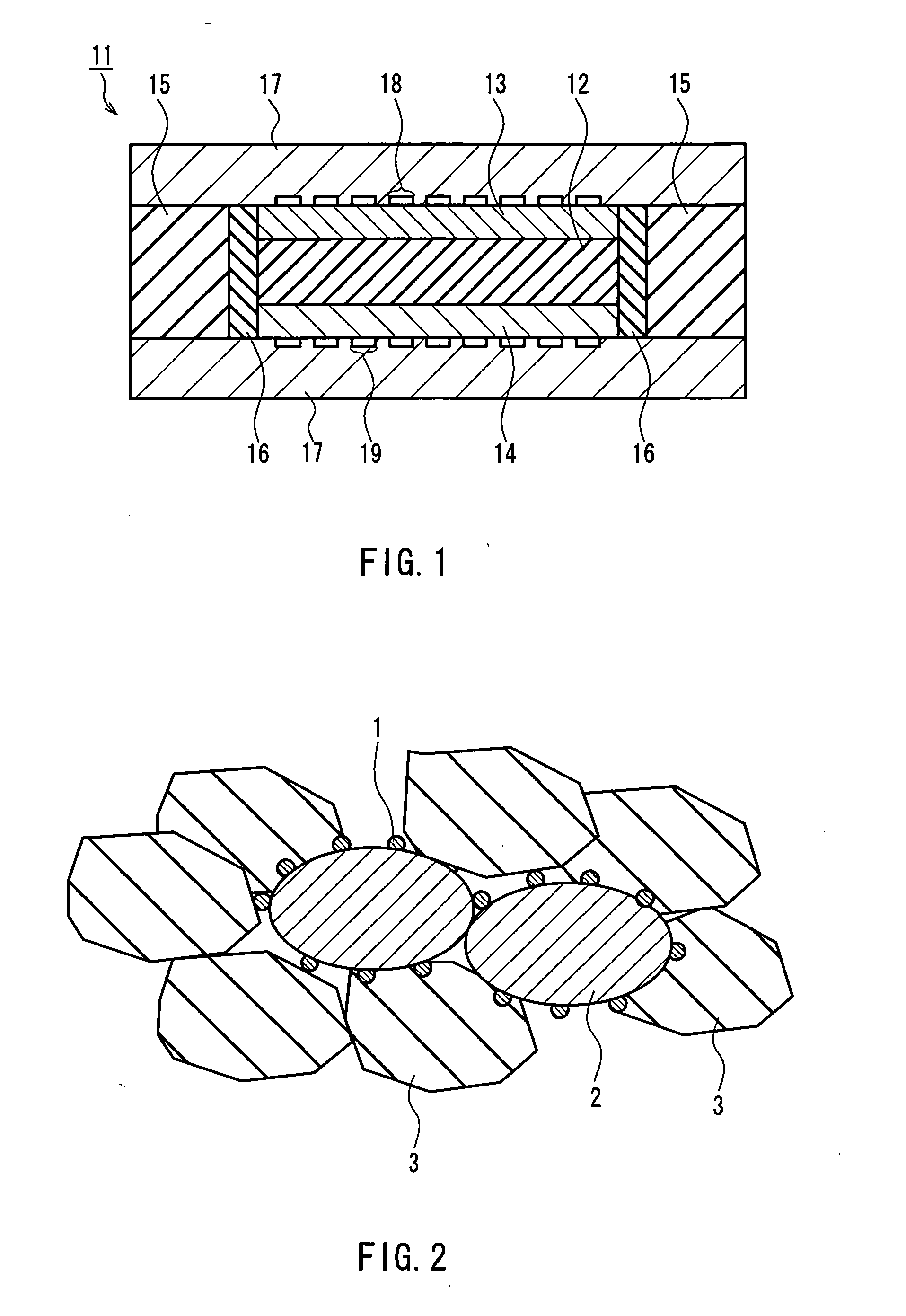
The present invention provides a solid oxide fuel cell with superior power generation characteristics even at lower temperatures (for example, in a range of 200° C. to 600° C. and preferably in a range of 400° C. to 600° C.) and a method for manufacturing the same. The solid oxide fuel cell is such that the solid oxide fuel cell includes an anode, a cathode, and a first solid oxide held between the anode and the cathode, the anode includes metal particles (2), an anode catalyst (1), and ion conducting bodies (3), the anode catalyst (1) is attached to the surface of the metal particles (2), and the first solid oxide and the ion conducting bodies (3) have either one of an ionic conductivity that is selected from oxide ionic conductivity and hydrogen ionic conductivity.

Description

TECHNICAL FIELD [0001] The present invention relates to solid oxide fuel cells and methods for manufacturing the same. BACKGROUND ART [0002] Solid oxide fuel cells (SOFCs) are fuel cells using solid oxide having ionic conductivity as the electrolyte. Generally, yttria-stabilized zirconia (YSZ) is used as the solid oxide, and YSZ conducts oxide ions to generate electrical power. When YSZ is used as the electrolyte, the power generation temperature is usually at least 800° C. [0003] The solid oxide, which is an electrolyte, is held by an anode and a cathode. A porous cermet made from a solid oxide such as YSZ and metal particles such as nickel generally is used as the anode. Furthermore, a conductive porous body made from a solid oxide such as YSZ and lanthanum manganite, for example, generally is used as the cathode. The electrodes have catalytic activity and the transfer of oxide ions (depending on the type of the electrolyte, the transfer of hydrogen ions) through the electrolyte i...

Claims


Application Information

Patent Timeline
IPC IPC(8): H01M8/10H01M4/86H01M6/00H01M4/88H01M4/90H01M4/92H01M8/02H01M8/12
CPCH01M4/8605H01M4/8636H01M4/8652H01M4/8875H01M4/8882Y10T29/49115H01M4/905H01M4/921H01M2004/8684Y02E60/50H01M4/90
Inventor SHIBUTANI, SATOSHIOKADA, YUKIHIROYUASA, KOHJITANIGUCHI, NOBORUMINO, NORIHISANIIKURA, JUNJI
Owner PANASONIC CORP
Learn More