Retractor and distractor system for use in anterior cervical disc surgery

Active Publication Date: 2006-04-20
NEHLS DANIEL G
View PDF30 Cites 117 Cited by
  • Summary
  • Abstract
  • Description
  • Claims
  • Application Information

AI Technical Summary

Benefits of technology

[0008] A first aspect of the present invention supplies an answer to the aforementioned need by providing a retractor which mates with and is held secu

Problems solved by technology

This procedure, however, does not provide consistent retraction, and surgeons have had to adjust the retractor blades repeatedly during the procedure, since the retractor is not stabilized firmly and tends to loosen or shift its position.
Conventional retractors tend to slip and to be torqued around from their intended positions and can tear paraspinous muscles or impinge harmfully on neck structures.
When retractors slip or

Method used


Image

  • Retractor and distractor system for use in anterior cervical disc surgery
  • Retractor and distractor system for use in anterior cervical disc surgery
  • Retractor and distractor system for use in anterior cervical disc surgery

Examples


Embodiment Construction

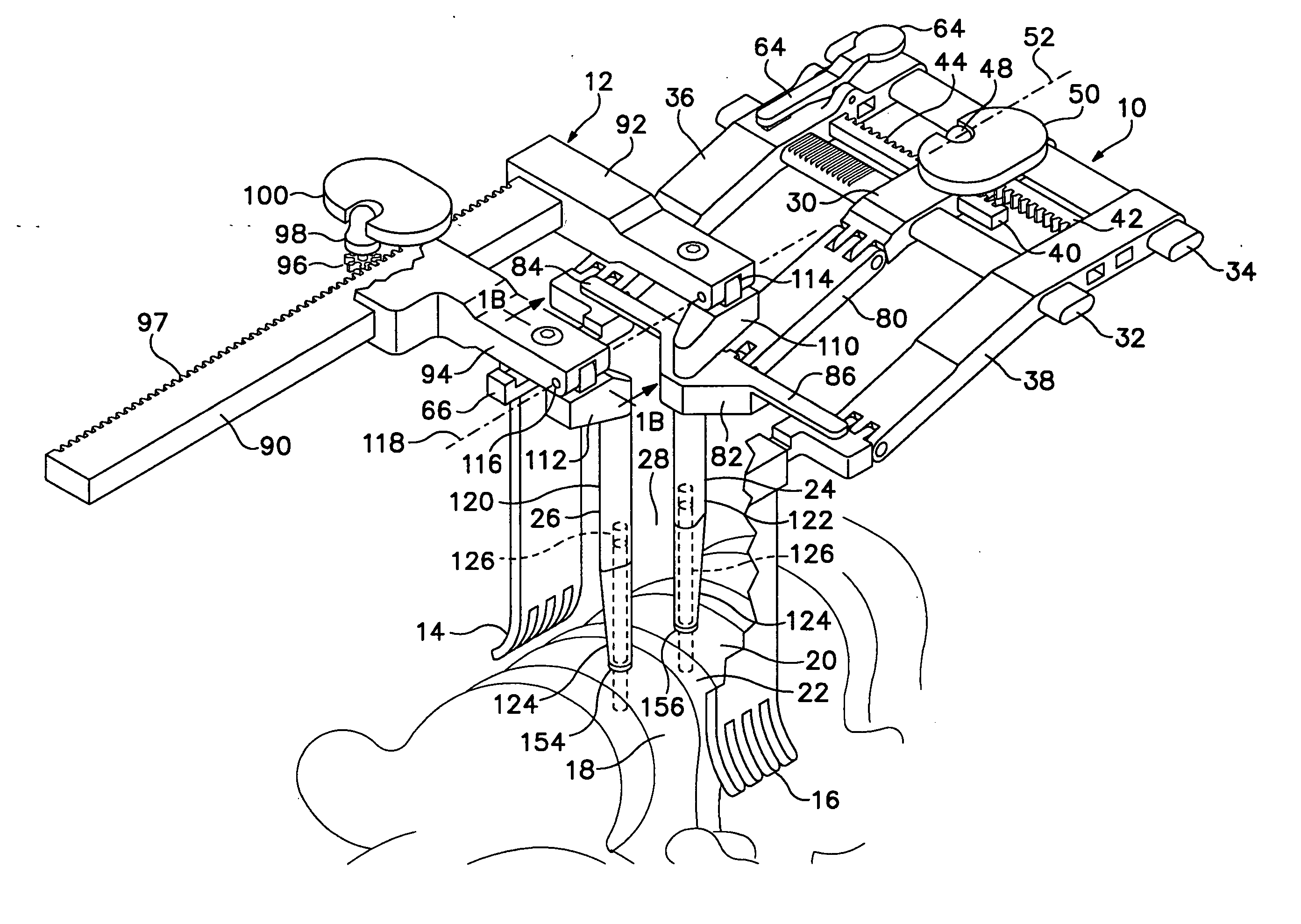
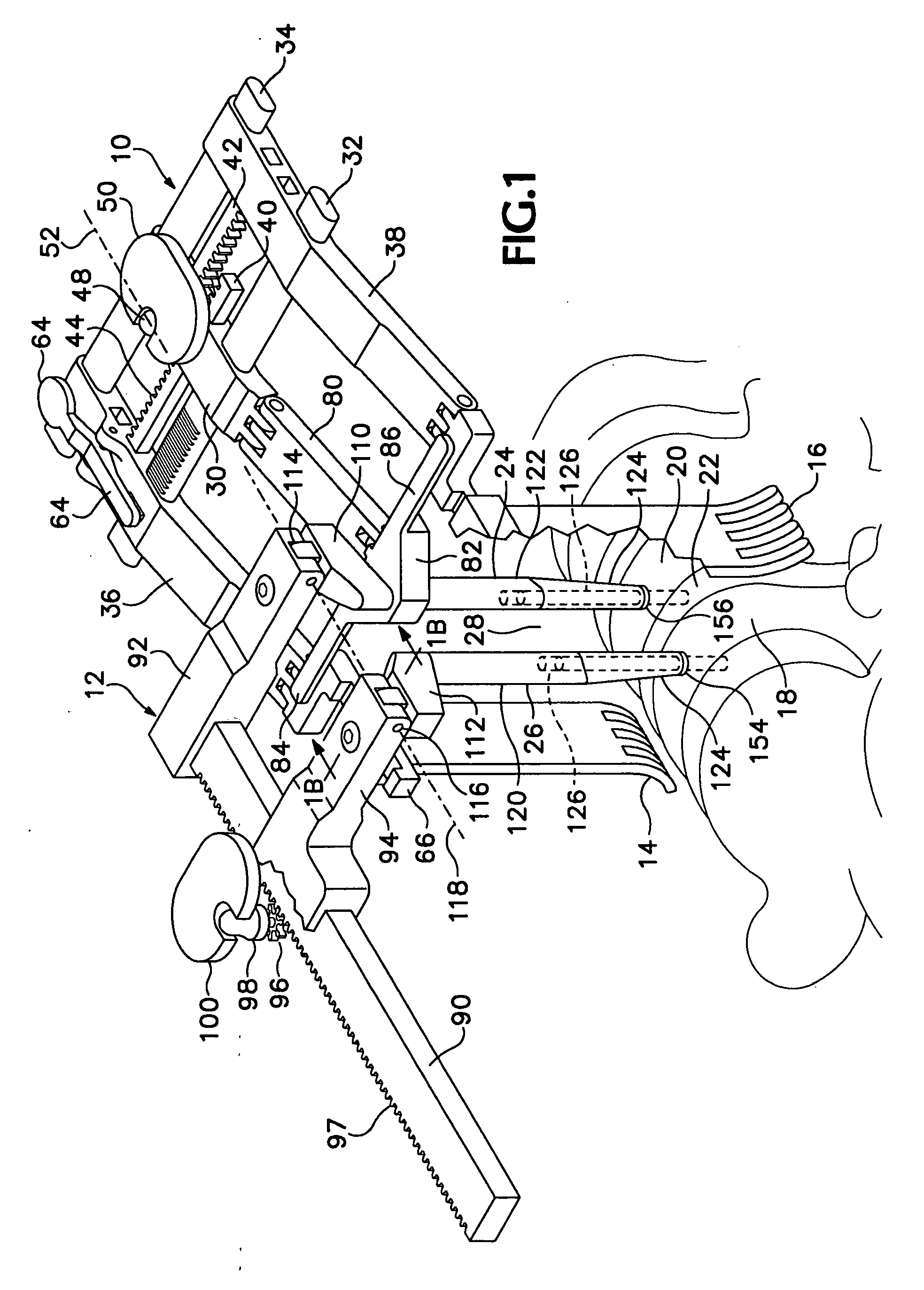
[0027] Referring now to the drawings which form a part of the disclosure herein, FIG. 1 shows a retractor 10 mated with and in use together with a distractor 12 in connection with a discectomy and cervical spinal fusion procedure. The retractor has blades 14 and 16, with blade 16 shown partially cut away in order to show more clearly how the distractor 12 is mated with the retractor 10.

[0028] The distractor 12 is engaged securely with a pair of vertebrae 18, 20 between which is a deteriorated disc 22.

[0029] The retractor 10 is securely mated to the distractor 12, so that the distractor 12, being fixedly located with respect to the vertebrae 18 and 20, keeps the retractor 10 in the position required to keep the structures of the patient's neck, such as the esophagus and trachea (not shown) on the medial side of the retractor and neck muscles and carotid artery (not shown) on the lateral side of the retractor. The retractor 10 provides a space 28 between the attached retractor blade...


PUM


Abstract

A retractor, a distractor, and a drill guide for use in performing anterior cervical discectomy and vertebral fusion. The distractor is located with respect to vertebrae to be fused by pins fastened in the vertebrae to be fused, and the retractor is mated mechanically with the distractor to hold the retractor in a required location. Blade carrying arms of the retractor are both moved toward or away from a central part of the retractor.

Description

BACKGROUND OF THE INVENTION [0001] The present invention relates to improvements in surgical tools and methods for their use by surgeons in performing anterior cervical discectomy and vertebral fusion, and in particular is related to a cooperative relationship between a retractor and a distractor. [0002] In recent years, deteriorated cervical discs have been surgically replaced with an artificial disc or a bone graft used to fuse together the vertebrae between which the deteriorated disc had been located. The space between the vertebrae is approached by retraction of the muscles and structures in the anterior neck, using a retractor having blades conventionally held apart by a spreading mechanism which may include a crank or scissors mechanism to spread the retractor blades apart from each other. The currently used technique consists of dissecting the medial aspect of each longus coli muscle, the muscles that are attached to and which run parallel to the spine on either side of the ...

Claims


Application Information

Patent Timeline
IPC IPC(8): A61B1/32
CPCA61B17/0206A61B17/025A61B17/0293A61B17/1757A61B17/7077A61B2017/0256
Inventor NEHLS, DANIEL G.
Owner NEHLS DANIEL G
Why Eureka
Try Eureka