Flex circuit shielded optical sensor

a shielded optical sensor and flex circuit technology, applied in the direction of printed circuit non-printed electric components, instruments, applications, etc., can solve problems such as brain damage and death

Inactive Publication Date: 2006-04-20
JPMORGAN CHASE BANK NA
View PDF99 Cites 158 Cited by
  • Summary
  • Abstract
  • Description
  • Claims
  • Application Information

AI Technical Summary

Problems solved by technology

Early detection of low blood oxygen level is critical in the medical field, for example in critical care and surgical applications, because an insufficient supply of oxygen can result in brain damage and death in a matter of minutes.

Method used


Image

  • Flex circuit shielded optical sensor
  • Flex circuit shielded optical sensor
  • Flex circuit shielded optical sensor

Examples


Embodiment Construction

Sensor Configuration

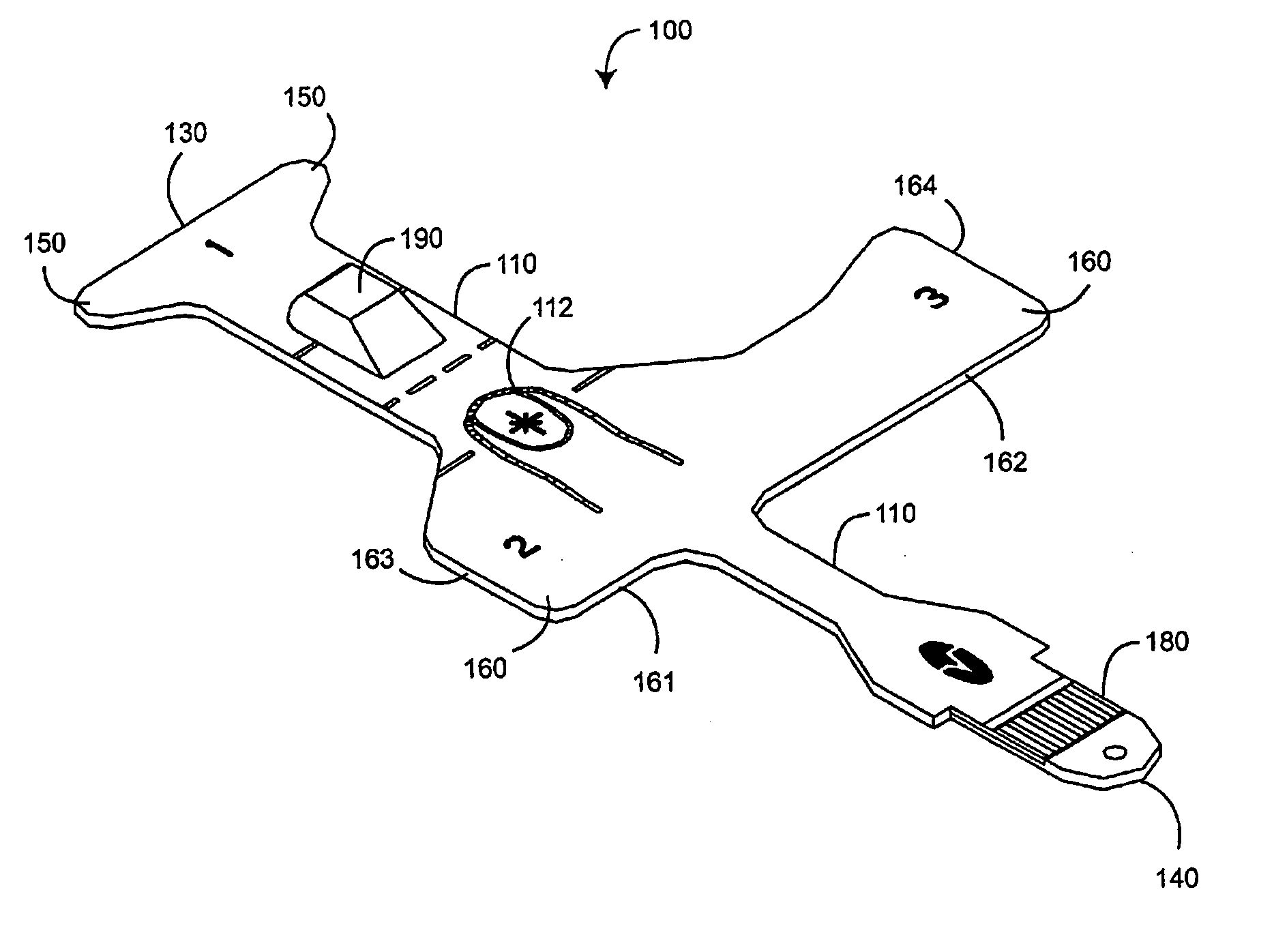
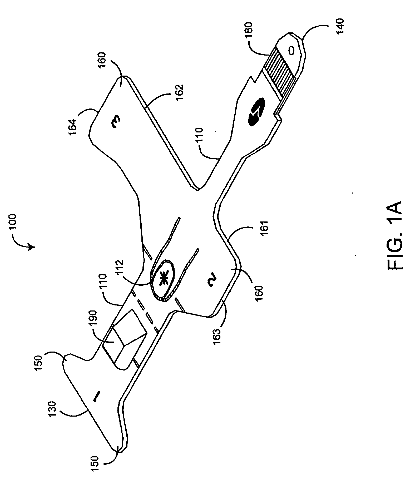
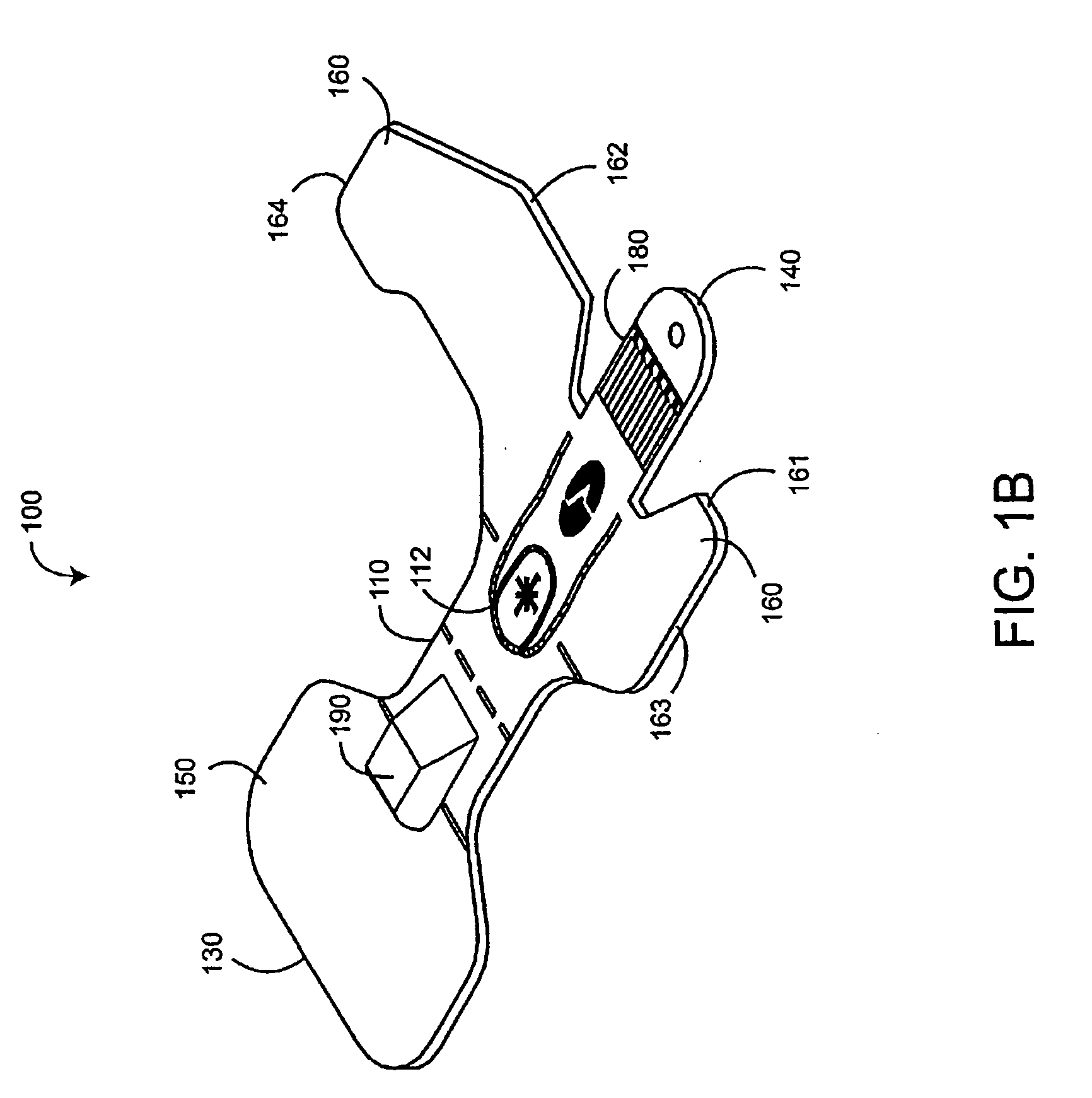
[0020]FIG. 1A illustrates one embodiment of a flex circuit shielded optical sensor. The sensor 100 has a central body 110, a foldover end 130, a connector end 140, a pair of adhesive end attachment wraps 150, a pair of adhesive middle attachment wraps 160, a connector 180 and a detector housing 190. The end wraps 150 and middle wraps 160 extend on either side of the central body 110 and are used to attach the sensor 100 to a patient's finger, in a manner similar to that described in U.S. Pat. No. 5,782,757 entitled “Low Noise Optical Probe,” which is assigned to the assignee of the present invention and incorporated by reference herein. The central body 110 retains a flex circuit assembly 200 (FIGS. 2A-B), described in detail below. The flex circuit assembly 200 is a portion of a sensor core assembly 800 (FIG. 8A-B), which is sandwiched into a completed sensor 100, as described in detail with respect to FIGS. 8-10, below.

[0021] As shown in FIG. 1A, an emitter ...


PUM

PropertyMeasurementUnit
optical radiationaaaaaaaaaa
conductiveaaaaaaaaaa
electricallyaaaaaaaaaa

Abstract

A flex circuit optical sensor has an integrated Faraday shield. A conductive trace layer disposed on a substrate is used to form a conductive grid which shields the face of a photodetector. A conductive ink layer is formed on a substrate side opposite the trace layer. The back and sides of the detector are shielded by flex circuit flaps that have the conductive ink layer but substantially exclude the trace layer so as to fold over and closely adhere to the detector body. The shielded substrate flaps advantageously eliminate a separate detector shield, which is typically fabricated with an etched copper part that must be attached to a flex circuit before mounting the detector.

Description

CROSS-REFERENCE TO RELATED APPLICATIONS [0001] This application is a continuation of and claims a priority benefit under 35 U.S.C. § 120 to U.S. patent application Ser. Number 10 / 137,942, filed May 2, 2002, which claims a priority benefit under 35 U.S.C. § 119(e) from U.S. Provisional Patent Application Nos. 60 / 288,324 entitled “Pulse Oximeter Sensor Attachment Flap,” filed May 3, 2001 and 60 / 301,183 entitled “Flex Circuit Shielded Optical Sensor,” filed Jun. 27, 2001. The disclosures of the aforementioned patent and applications are incorporated herein in their entireties by reference.RELATED COPENDING APPLICATIONS AND PATENTS [0002] This application is related to the disclosure in copending U.S. patent application Ser. No. 11 / 172,587, entitled “Optical Sensor Including Disposable and Reusable Elements,” filed Jun. 30, 2005, and the disclosure in U.S. Pat. No. 6,671,531, entitled “Sensor Wrap Including Foldable Applicator,” all of which are commonly owned by the Assignee of the pre...

Claims


Application Information

Patent Timeline
Patent Type & Authority Applications(United States)
IPC IPC(8): A61B5/00H05K3/10G01N21/01A61B5/024A61B5/145A61B5/1455G01N21/35H01L31/02H01L31/12H05K1/02H05K1/18
CPCA61B5/02427A61B5/14552A61B5/6826A61B5/6833Y10T29/49155A61B2562/12A61B2562/182H05K1/0218H05K1/189A61B5/6838
Inventor MASON, GENEAL-ALI, AMMARGERHARDT, THOMAS J.
Owner JPMORGAN CHASE BANK NA
Why Eureka
Try Eureka